Hardware Hacking With JavaScript
The Internet of Things (IoT) has enabled the Internet to reach beyond the browser. Made up of electronically networked devices, these “things” are able to interact with the physical world via sensors that feed data they capture back into their ecosystems.
Currently, these devices are mostly products, designed with a specific purpose in mind, a typical example being a fitness band that tracks activity. It reports the information gathered to an app, which is then able to analyze the data and offer suggestions and motivation to push the user further.
When building IoT devices, the task is typically divided between two roles: A hardware engineer creates the physical device, and a developer the ecosystem. However, this is not always necessary. In the case of JavaScript, its isomorphic nature allows for one language to be used across multiple platforms — including hardware.
This is George, the talking plant, a (rather grumpy) addition to the Internet of Things. His sensors gather data on his surroundings, including the soil’s moisture level, ambient temperature and light intensity. With his 8 × 8 LED face, he is able to visualize his displeasure and, using HTML5’s Web Speech API, to sarcastically answer your mundane questions. George is a great example of how it is possible to use web technologies, fused with hardware, to deliver new and engaging experiences.
This article covers the basics of how to get started building for your own IoT devices using JavaScript.
Getting Started
Building hardware prototypes and Internet-connected devices has traditionally been something that only electrical engineers would have attempted. This changed with the appearance of development boards such as Arduino UNO, Particle (formerly Spark Core) and Raspberry Pi.
Development boards mimic a motherboard on a computer. They have input and output sockets, such as USB and power, as well as pin boards that allow you to add external components. A microcontroller chip acts as the processor, running the application’s code and communicating with the inputs and outputs. This chip is relatively slow, specifically designed to perform simple tasks such as reading sensor data. However, it also has the ability to switch, making it possible to change the power supply of lights, motors and many more components.
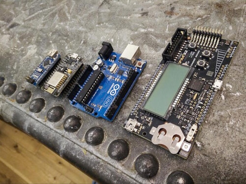
The maker movement has been gaining traction in the last few years, and building IoT devices has become big business. This has expanded the market of development boards, and there is now a wide range on offer, each with its own features. Competition has caused many to focus on unique selling points, such as wireless communication (with Wi-Fi and Bluetooth chips), size and battery life. When architecting your own devices, you will need to consider which physical attributes you require. Likewise, software will also factor into the decision, such as the programming language you can run on the board. Research thoroughly and choose the board that best suits your needs.
In the examples featured here, we’re using Arduino UNO. This particular development board is probably the most popular on the market because it is very easy to use. If you are just getting started, we would recommend buying a starter kit, something along the line of what is offered by Arduino. It will come with compatible components for your chosen development board and usually a lot of documentation to help you get started.
The Basics Of Electricity And Circuits
As the name suggests, an electronic circuit is circular. Electrons flow from the positive end of the power source (for example, a battery) around the circuit to the negative end of the same power source.
The easiest way to understand the physics of what is happening inside an electric circuit is to compare it to a water tank system. Water in a pipe flows just like electrons in a wire. These electrons are what form the electric current that powers the components of the circuit.

Just as the amount of water stored in the tank affects the pressure on the tap, the more electrons there are in the power source, the more it’s charged. This is the voltage. The higher the voltage, the more electrical pressure exists between the negative and positive poles, controlling the velocity of the electrons around the circuit.
Just like a volume of water flowing through a pipe, the current of a circuit refers to the number of electrons flowing through the wire. This is important when building a circuit because you’ll need to make sure that each component is receiving enough to perform its task. Current is measured in amperes, or amps (A), and can give us information on the amount of electrons used. For example, if a motor consumes 100 milliamperes (mA) and a battery has a capacity of 1000 milliamperes per hour (mAh), then we can run the motor for 10 hours on a single charge.
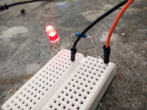
When components in a circuit require less current to run than there is in the circuit, they can receive too much power and break. In this situation, resistance needs to be introduced to prevent this from happening. Using our water analogy, the diameter of a pipe will limit the amount of water that can flow through it, just like resistance limits the flow of electrons.
Resistors are the components used to reduce current. They vary in the amount of resistance they apply, shown by the colored bands on the outside of the resistor. The different colors represent different numbers, and adding these bands together will reveal the resistance of that particular resistor. (Calculators are available!) The higher the value, the more resistance is applied to the circuit and the less likely you will cause damage to your component. Using Ohm’s law — resistance equals voltage divided by current (or R = V / I) — you can calculate the exact resistor needed in a circuit.
Hello World
With the basics covered, we can look at a simple example to visualize how it all fits together. We will be undertaking the “Hello World” of hardware development: making an LED blink.
As mentioned, you can use any one of multiple development boards. In this example, we will be using Arduino UNO. We will also be using a Mac running Mac OS X, but all of the examples should also run on Windows.
The Hardware
You will need:
- 1 × Arduino UNO
- 1 × solderless breadboard
- 1 × standard LED
- 1 × 220 Ohm resistor
- 2 × jumper cables
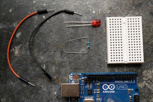
This includes a few components that haven’t yet been mentioned:
- Jumper cables are used to direct the flow of electrons, just as any wire is used in a circuit.
- LED is short for light emitting diode, which is essentially a small bulb. It has one long leg and one short leg. The longer leg signifies where the positive flow of the circuit should enter, and the shorter leg the negative output. If you get these the wrong way around, the LED will not light up.
- A solderless breadboard (the white block with holes) is a prototyping tool that allows for the creation of circuits without the need for soldering, making it possible to easily change and correct a circuit, as well as to reuse components. These come in many different shapes and sizes, but all perform the same role.
The image below shows the flow of current. Components can be used to link sections together, as the LED and resistor do in the following example. On larger breadboards, the outside vertical lines are commonly used for connecting the positive and negative jumper cables to give separation to the circuit that you are designing.
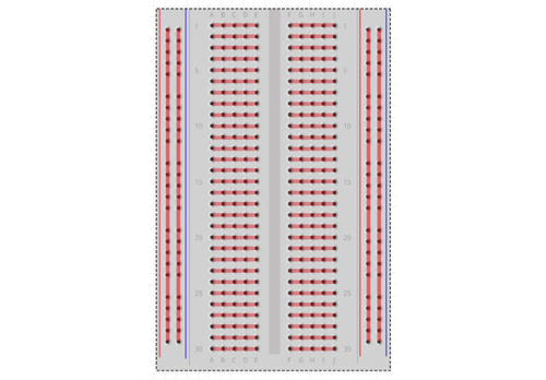
Insert your components as detailed by the schematic below — matching pin for pin. This will make things easier when continuing in the next section.
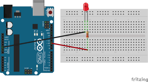
To start the circuit, connect a jumper wire from pin 10 on the Arduino. This is the point at which the Arduino starts talking to the circuit. You can use any numbered pin from the right side of the Arduino — just make sure your code refers to the correct one.
To make sure the ideal amount of current flows through the LED, the resistor is needed. Unlike the LED, it doesn’t matter which way it is inserted into the circuit.
Whether pin 10 is allowing current through or not (controlled by your code) will determine whether the LED is on or off.
Another jumper wire then connects to the negative side of the LED and returns to ground to complete the circuit. Simple!
Once completed, your circuit should look something like the image below. Plug this into your computer via USB. The next task is to set up the Arduino to work with JavaScript.
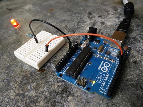
Before writing any software, we need to make sure the Arduino has the correct firmware so that it will work with JavaScript. The firmware essentially exposes an API for the computer, so that the code can interact with the board through the USB port.
Download and install the integrated development environment (IDE) from the Arduino website. Next open up the IDE, ensuring your Arduino is plugged in via USB.
Before running anything, you also need to check that you have the correct USB port. Go to “Tools” → “Port.” The names can differ, so a good rule is to choose a port that has “tty” and “usb” in its name on Mac OS X and “COM” on Windows.
Once completed, you can now upload the firmware. Select “File” → “Examples” → “Firmata” → “Standard Firmata.” Once done, select “File” → “Upload on Mac” (or “Sketch” → “Upload on Windows”).
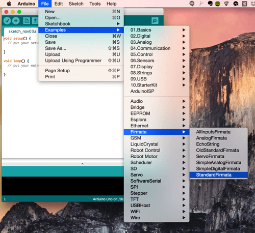
Now it’s time to write some JavaScript!
The Software
To control the LED with JavaScript, we will need to use a library built for Node.js called Johnny-Five. Basically, it’s a library built by the team at Bocoup to make building hardware more accessible to the web community. If you don’t know what Node.js is or how to use it, Elliot Bonneville has a great introduction on this very website.
Because the core of our example uses an Arduino, this library allows our machine to connect to the hardware through the USB port.
To get started, you will need to have Node.js installed. If it’s not, you can download it from the Node.js website. This will also install Node Package Manager (npm), which we will use to install all of the dependencies for the application. The example is run on a Mac, using Terminal as the command-line tool; however, because Node.js is multi-platform, this can work on any machine.
All of the code featured in this article is available on GitHub.
To install all of the dependencies required for this project, you will need to create a package.json file, which can be taken from the code below. This is a shopping list of the libraries required to get the example running. When the install command is initialized, npm will go out and get all of the ingredients needed for everything to run. This file must be in your root folder.
{
  "name": "Hardware-Hacking-with-JavaScript",
  "description": "Smashing Magazine - Hardware Hacking with JavaScript",
  "version": "0.0.1",
  "homepage": "https://www.james-miller.co.uk/",
  "keywords": ["arduino","tutorial","hardware"],
  "author": {
   "name":"James Miller & Mate Marschalko"
  },
  "repository": {
    "type": "git",
    "url": "git://github.com/jimhunty/Hardware-Hacking-with-JavaScript.git"
  },
  "bugs": "https://github.com/jimhunty/Hardware-Hacking-with-JavaScript/issues",
  "license": "MIT",
  "dependencies": {
    "johnny-five": "^0.9.13"
  }
}
In your command-line tool, ensure that you are in the same folder that you created for this example with the package.json file; then, run npm install. If you don’t have the permissions to install these packages, use sudo npm install instead.
Now, you need to create the application code to run our example. We have named this file blink-led.js. The comments detail what is going on.
// Johnny-Five is our JavaScript framework for accessing Arduino.
var jfive = require("johnny-five");
var board, led;

board = new jfive.Board();

// Similar to jQuery, we wait for the board to be ready.
board.on("ready", function() {

  // 10 represents the pin number that the LED is plugged into.
  led = new jfive.Led(10)

  // The LED blinks (i.e. turns on and off) every 1000 milliseconds.
  led.blink(1000);

});
First, the libraries are loaded, then the variables are initialized. A new Board instance is created using the constructor, and the on ready function will get the board warmed up and ready to receive instructions. Because you plugged the jumper cable that connects to the LED into pin 10, it needs to be defined in the led variable. The blink method is then used to turn the light on and off, in 1-second phases.
You now have everything you need to get this light show started — crank up the music! Make sure your Arduino is plugged in and the circuit is all set up. In the command line, run node blink-led.js, replacing the file name with whatever you have called your code. You should now have a blinking light.
Try modifying the code to make the light blink faster or slower. Each time you do, you will need to restart your code in the Terminal. You may wish to try led.pulse(); this will fade the LED in and out, instead of just switching with no transition.
Home Monitoring
Already you’ve learned a lot! Now you can put this knowledge to use and build a simple home-monitoring system, similar to commercial products like Nest and Hive.
This time, you’re going to be using a temperature sensor, connected to the Arduino from the Node.js server. The temperature will be read by the sensor and fed into a browser that will display the data on a simple web page.

The Hardware
You will need:
- 1 × Arduino UNO
- 1 × solderless breadboard
- 1 × TMP36 temperature sensor
- 3 × jumper cables
The temperature sensor chosen for this example is available in most starter kits and is incredibly cheap to purchase individually.
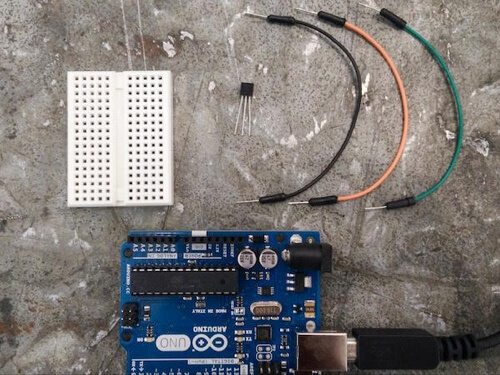
With the previous LED blink example, you set up the connection between the Node.js server running on the computer and the Arduino. This connection can also be used to read data from sensors connected to the Arduino.
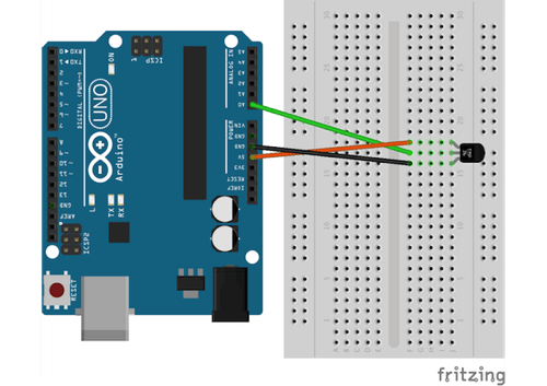
Above is the completed circuit. Try to match this pin for pin.
Be careful when handling the temperature sensor because it is easy to get the legs mixed up. The flat side of the component is the front and should be facing towards you as you wire up the sensor. Because each of the three legs has a different purpose, wiring them incorrectly will mean your circuit will not work.
The analog input pins are the five pins lined up along the left side of the board. The Arduino has both analog and digital pins, both input and output. Digital means there are only two states — on and off (or electric signal and no electrical signal) — and are great for buttons and other binary switches that interpret only two states. Analog input, on the other hand, can represent a range of values, and the analog input pins on the Arduino can measure any voltage between 0 and 5 volts (and produce a 10-bit value of that reading). The temperature reading from the sensor will be returned in a variable resistance measurement that is proportional to the air temperature.
Connect the signal pin in the middle of the sensor to the analog input A0. Connect the left pin to the 5V pin (positive) and the right pin to ground (negative) to complete the circuit.
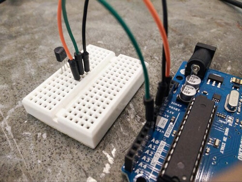
Your circuit should now look something like the picture above. Next, you need to create a new file to read the temperature sensor. This file will start in the same way as in the previous example, loading the Johnny-Five library, initializing a new board instance and then adding an on ready event listener.
var jfive = require("johnny-five");

board = new jfive.Board();

board.on("ready", function() {
  // We create a new sensor instance and define the sensor type and the pin it’s connected to.
  var tempSensor = new jfive.Thermometer({
    controller: "TMP36",
    pin: "A0"
  });

   // We add an event listener to the sensor and handle the incoming data.
  tempSensor.on("data", function() {
    // The data object also has a fahrenheit property, if that’s what we are after.
    console.log(this.celsius + "°C");
  });

});
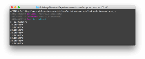
Save this piece of code as temperature.js, and run it from the console by typing in node temperature.js.
Because console.log was used in the code, the readings will be outputted to the Terminal for debugging.
Servers And Sockets
Now you have a working thermometer running in Node.js. This simple example alone opens up a whole range of possibilities if you consider all of the different Node.js modules available to process and use this data. You could save this to a Google Spreadsheet, tweet or write about it, or even stream this data to the browser in real time with WebSockets — which is what you are going to do next!

To establish the connection with the browser and to stream the sensor data, we’ll need to start a Node.js HTTP server to serve our HTML document, and then open the WebSocket connection between them. Starting up a web server in Node.js is relatively simple with the Express library. First, install it from the Terminal:
npm install --save expressOnce it’s installed, these lines of code will instantiate the server:
// Load libraries and then initialize the server.
var app = require('express')();
var http = require('http').Server(app);

// When the user requests the root of the page (/), we respond with index.html.
app.get('/', function(req, res){
  res.sendFile(__dirname + '/index.html');
});

// We listen for connections on port 3000.
http.listen(3000, function(){
  console.log('listening on *:3000');
});
Save this as a server.js file.
In this server code, the first two lines load the required libraries and create an HTTP server instance. Next, simple routing logic serves the index.html file from the project’s folder when the user requests the root (/). Finally, port 3000 listens for connections.
To test this, create a standard index.html file in the root of the project’s folder. In the command line, navigate to your project’s folder and type node server.js. If you then type https://localhost:3000 or the IP address of your machine and the port (for example, https://190.140.0.00:3000) in a browser, you should see your standard index.html page. This means your server is all set up.
This was definitely easier than configuring an Apache server!
Before merging this piece of code with the temperature.js file, we’re going to set up the WebSocket connection.
A WebSocket makes it possible to open a communication session between the browser and the server. With this API, you can send two-way real-time messages and receive event-driven responses without having to poll for a reply. Socket.IO is the Node.js module that you are going to use to establish and handle this connection. Install Socket.IO just like you installed Express and Johnny-Five:
npm install --save socket.ioNotice how your package.json file is now updated with Express and Socket.IO under dependencies? This means that whoever wishes to run your application from their machine can simply run npm install, and all of the module dependencies that you loaded will be installed at once. Nice! Now you can add the WebSocket functionality to the working server.js code. Below is the full example:
var app = require('express')();
var http = require('http').Server(app);
// Load the Socket.IO library.
var io = require('socket.io')(http);

app.get('/', function(req, res){
  res.sendfile('index.html');
});

// Establish the WebSocket connection with the browser.
io.on('connection', function(socket){
  console.log('a user connected');
});

http.listen(3000, function(){
  console.log('listening on *:3000');
});
First, Socket.IO is loaded, and then an on connection event listener is created. This will be triggered when a user loads the index.html file.
On the index.html page, the Socket.IO client-side library needs to be initialized in order to talk with the server. To prepare your HTML file for this, add the piece of code below right before the closing body tag:
<script src="https://cdn.socket.io/socket.io-1.2.0.js"></script>
<script>
  var socket = io();
</script>
The connection should now be set up, and you should see the “A user has connected” message in the command line upon loading the index page via the localhost link.
Now, you can send messages to the browser from the server with the socket.emit() function. You can do this by replacing the previous function in server.js:
io.on('connection', function(socket){
  console.log('a user connected');
  socket.emit('Server message', “Hello from the server!”);
});
This is how you need to modify index.html to receive the message:
<script src="https://cdn.socket.io/socket.io-1.2.0.js"></script>
<script>
  var socket = io();
  socket.on('Server message’, function (message) {
   console.log(message);
  });
</script>
If you’ve done everything correctly, you should see the “Hello from the server!” message in your browser’s console. Congratulations! This means you have set up a real-time WebSocket connection between a Node.js HTTP server and a browser!
This is really quite useful, and not just for this project. A WebSocket connection can be used to communicate between multiple browsers to create chat applications, multiplayer games and much more!

Now it’s time to merge the temperature.js file, which handles communication with the Arduino, with our new WebSocket server code, which is responsible for connecting to the browser.
This requires extending server.js:
var app = require('express')();
var http = require('http').Server(app);
var io = require('socket.io')(http);
var jfive = require("johnny-five");
var board = new jfive.Board();

var board, socket,
      connected = false;

app.get('/', function(req, res){
   res.sendFile(__dirname + '/index.html');
});

io.on('connection', function(s){
   console.log('A user has connected');
   // Tracking connection
   connected = true;
   // Saving this for the board on ready callback function
   socket = s;
});

board.on("ready", function() {
   console.log('board has connected');

   var tempSensor = new jfive.Thermometer({
      controller: "TMP36",
      pin: "A0"
   });

   tempSensor.on("data", function() {
      // We send the temperature when the browser is connected.
      if(connected) socket.emit('Temperature reading', this.celsius);
   });
});

http.listen(3000, function(){
   console.log('listening on *:3000');
});
Here, you have simply copied over from temperature.js the line that loads Johnny-Five and initializes the board, as well as the whole board on ready function.
You’ve also added two new variables: one to keep track of WebSocket connections and another to store the socket instance for other functions to be accessible — in this case, for the board on ready function that uses it to send and receive messages.
Now, the index.html file needs to be updated to handle the data coming through the socket connection Temperature reading. The code below needs to be added to the HTML document within the script elements where the Server message handler previously existed.
socket.on('Temperature reading', function (message) {
console.log(message);
});
The Interface
The last thing to do is add a few lines of HTML and CSS to index.html to display the temperature reading in a user-friendly way. You’re also going to update the background color, making it change between blue (cold) and orange (hot), according to the temperature. The HTML is very simple: just one h1 element to hold the number.
The following needs to be added to the body.
<h1 class="temperature">0ºC</h1>A large thin typeface should work very well with the numbers; try Lato, a free font from the Google Fonts library. Load this in the head section of the document:
<link href='https://fonts.googleapis.com/css?family=Lato:100' rel='stylesheet' type='text/css'>The styling is minimal in this example. The only tricky bit is the way the temperature label is loaded. It grabs the class name with the content CSS property and adds it to the :before pseudo-element.
body {
    background-color: hsl(0, 60%, 65%);
    transition: background-color 1s;
}

h1 {
    font-family: 'Lato', sans-serif;
    font-size: 120px;
    font-weight: 100;
    color: white;
    text-align: center;
    margin: 60px;
}

h1:before{
  content: attr(class) ":";
  font-size: 22px;
  position: relative;
  top: -69px;
  left: 0;
  text-transform: uppercase;
}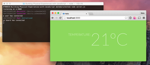
This looks pretty already!
To finish it off, add a few lines of JavaScript to update the values when receiving the WebSocket message, and to change the background color.
<script src="https://cdn.socket.io/socket.io-1.2.0.js"></script>
<script>
  var socket = io(),
  temperature = document.querySelector(".temperature");

  socket.on('Temperature reading', function(message) {
      // Rounding down the decimal values and adding ºC
      temperature.innerHTML = parseInt(message) + "ºC";

      // Calculating the hue for the background color and changing it
      var hue = 200 - (parseInt(message) * 5);
      document.body.style.backgroundColor = "hsl(" + hue + ", 60%, 65%)";
  });
</script>
You’re done! The Arduino temperature readings will now show in real time in the browser.
Conclusion
While the prospect of building your own hardware can be daunting, hopefully, after working through these two examples, you’re already thinking about the possibilities and planning your next project. Many components are compatible with the Johnny-Five library, meaning that the only limit is your imagination.
Resources
- “Hardware Hacking With JavaScript,” James Miller and Mate Marschalko, GitHub
All of the code needed for this project - Johnny-Five, Rick Waldron, GitHub
A “JavaScript robotics programming framework” - Web on Devices, Mate Marschalko
A website on electronics hacking with JavaScript and other web technologies - Make
An online magazine by Maker Media aimed at makers, offering new projects as well as tips - Arduino Experimenter’s Guide for Node.js
More JavaScript and Arduino projects with Johnny-Five
Further Reading
- Choosing The Right Prototyping Tool
- How To Prototype IoT Experiences: Building The Hardware
- Prototype IoT Experiences: Configuring The Software
- iOS Prototyping With TAP And Adobe Fireworks


