Developing For Virtual Reality: What We Learned

Email Newsletter
Weekly tips on front-end & UX.
Trusted by 182,000+ folks.
 Register for Free
 Custom Web Forms for Angular, React, & Vue. Your backend.


 Celebrating 10 million developers
With the tools getting more user-friendly and affordable, virtual reality (VR) development is easier to get involved in than ever before. Our team at Clearbridge Mobile recently jumped on the opportunity to develop immersive VR content for the Samsung Gear VR, using Samsung’s 360 camera.
The result is ClearVR, a mobile application demo that enables users to explore the features, pricing, interiors and exteriors of listed vehicles. Developing this demo project gave us a better understanding of VR development for our future projects, including scaling, stereoscopic display and motion-tracking practices. This article is an introductory guide to developing for VR, with the lessons we learned along the way.
Developing For Virtual Reality
VR is one of the most stimulating and exciting new fields to develop for. It gives creators the freedom to bring their ideas to life. Any developer can create content for VR. The only requirement is a yearning for innovation and problem-solving. When first developing for VR, creators must consider the different UI, how to scale for a 3D environment and the devices they’re working with. VR brings together several technologies, including 3D stereoscopic displays, motion-tracking hardware, new input devices, computers and mobile phones.
Further Reading on SmashingMag:
- Getting Started With VR Interface Design
- Gamification And UX: Where Users Win Or Lose
- True Lies Of Optimistic User Interfaces
- Designing Card-Based User Interfaces
A main challenge when developing for VR is understanding what the user will expect to do and how you’ll be able to meet and exceed their expectations. Many factors, including performance, UI and scaling, play a huge part in upholding the user’s experience. Basic elements of 2D applications can’t be applied in VR content, so you need to know how the user will behave once they enter the virtual environment, and then develop accordingly.
Technology And Tools Used
Here are the prerequisites for VR development:
- Resources
Samsung GVRf, 360 HDRI images (which you can either purchase online or find free online), GVRf Demos, Samsung SDK. - Hardware
Samsung Gear Galaxy Note 4, 5, S7, S6 Edge, Edge+ or S7 Edge; Samsung Gear VR headset: Samsung 360 camera; Android phone that is 4.4 or newer and whose API level support is 19. You’ll want to use devices that have a lot of RAM, to push more polygons. - Tools
SourceTree, GitHub, TurboSquid, Android Studio and Gradle.
Getting Started
Unity has several features that makes Android development easier, especially for creating games, but the GearVRf is a good choice to consider if you’re on a tight budget. The GearVRf is a native Java framework created by Samsung and released as an open-source library.
Gear VR is a headset that combines Oculus’ optic lenses with new head-tracking technology that houses a mobile phone with a high-resolution display. It was released by Samsung in late 2014 at 199 USD and can be purchased through Samsung’s online store. Gear VR’s housing has several intuitive input controls, including an eye-adjustment wheel, as well as other controls, such as volume buttons, a headphone jack and a trackpad. It offers a better experience than DK2, with a nice form factor and fantastic display resolution.
To begin, we followed “Build Configuration for Android Studio” in the “GearVRf Developer Guide.” These steps got us to a good base point, until we hit an error: The native development kit (NDK) build command couldn’t be found in Android Studio. To circumvent the issue, we used a command line to remove the automatic build, which recognized the NDK immediately. We used Terminal with an NDK-Build command, which was packaged with the GearVR SDK that was failing in the Android Studio environment when trying to build. We succeeded in using it outside of Android Studio to build all of the SDK files the first time, which were then packaged in our repository. The command was removed from the build steps so that it wouldn’t fail every time our program was compiled and used the compiled SDK files instead. For development alternatives, we also considered Unreal Engine and Unity, but decided that Samsung’s GearVR framework was the best choice for us in terms of ease of use and budgetary restrictions.
We looked at Samsung’s GearVRf and existing demos to identify the inconsistencies in previous VR content, such as fragmentation, low pixel density, low frame rate and overall poor user experience. To increase the quality of your content, it’s crucial to optimize your code as much as possible for a seamless and nausea-free user experience. To achieve this, reduce faces that won’t be seen by the user, limit overdraws to optimize the graphics processing unit (GPU), and limit the level of detail in objects. Sample GearVRf applications, available in the GearVRf SDK, can provide you with valuable insight for writing your own VR applications.
Next, our product team defined the product in a discovery session. They mapped out what features the mobile app would have and created a road map to guide our development team. These features included a 3D model of each car exterior, with the ability to enter the car to see a 360 interior. They also wanted the app to showcase the car’s description and special features in a text box above the car model. From this, we determined what we knew we could do and what was possible with the resources we were working with. Most importantly, we wanted our VR application to have a smoother user experience, with high-quality content. Samsung’s 360 camera helped us create more compelling visuals, which are essential to making the experience truly immersive. With a rough idea from our product team, we laid out the architecture of the app and decided which scenes to include and created a basic code structure from there.
Basic Terminology
- Mesh
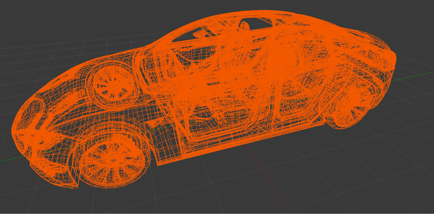
There are several ways to draw 3D graphics, but the most common is to use a mesh, which is an object composed of one or more polygonal shapes, constructed out of vertices (x, y, z) that define coordinate positions in the 3D space. The polygons typically used in meshes are triangles (three vertices) and quads (four vertices). Note that 3D meshes are often referred to as models. - Polygon count
The polygon count, also known as the polycount, is the number of faces in the object that you’re modelling. The higher the polygon count, the higher the file size and the longer the rendering time your project will take. To optimize the VR experience (depending on the devices you’re using), simplify the polygon count to increase the frame rate. - Textures and materials
The surface of a mesh is defined using additional attributes beyond the x, y and z vertex positions. Surface attributes can be as simple as a single solid color, or they can be more complex, such as light reflecting off of an object. Materials are the surface properties of a mesh and depend on the light in the scene. - Bounding box
A bounding box is a simple geometric box that is represented with three-dimensional points, with the minimum and maximum coordinates located diagonally from the bottom-left to upper-right corners of the object. A bounding box is created as mesh meta data and, in most cases, works best for selecting and choosing an object. Essentially, it’s a box placed around an object that enables the user to select the object with greater ease. - Stereoscopic displays
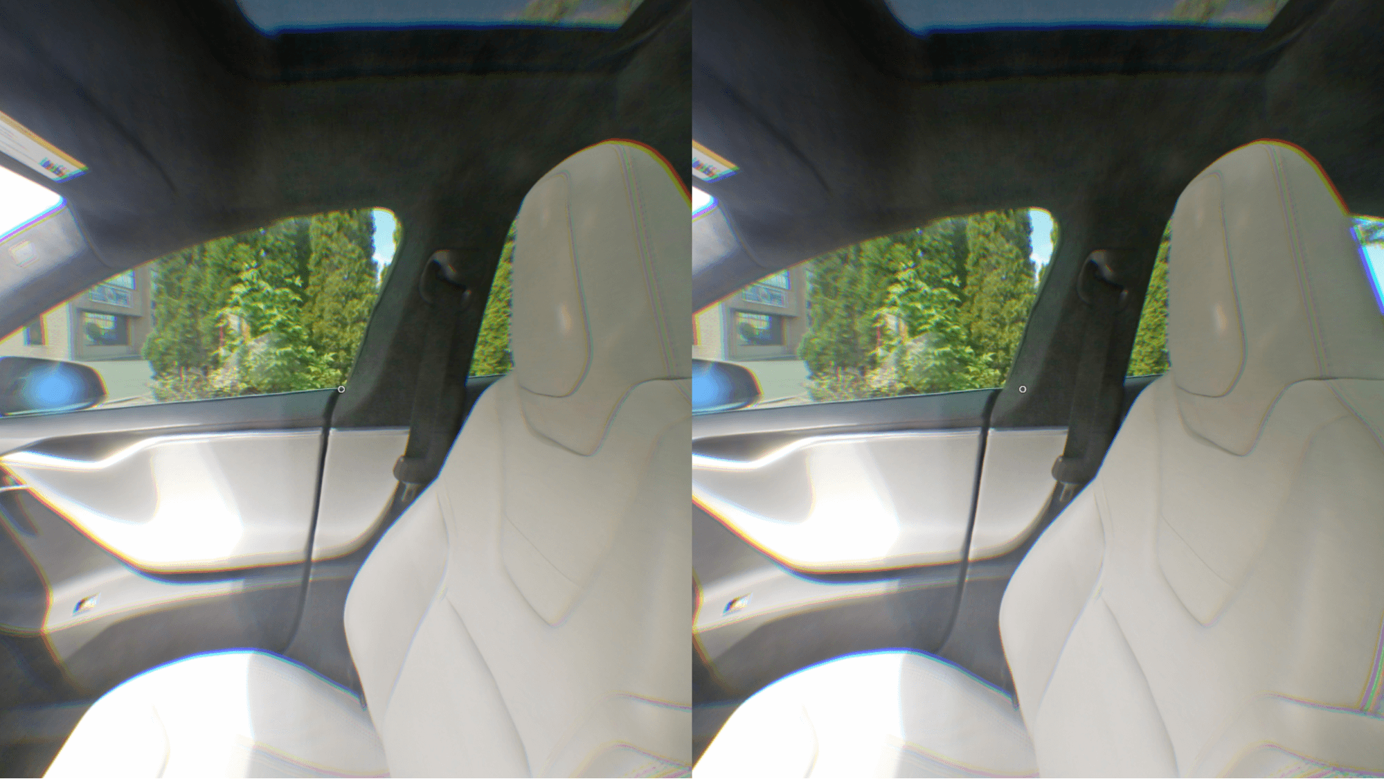
VR is about creating a 3D visual representation of an experience that conveys a sense of depth. To create depth, VR hardware systems such as the Gear VR headset employ a 3D display, also known as a stereoscopic display or head-mounted display. To create an illusion of depth, developers must generate a separate image for each eye, one slightly offset from the other eye. This creates a parallax effect (where the brain perceives depth based on the difference in the position of objects). Many VR headsets on the market now use barrel distortion to achieve this effect. - Motion-tracking hardware
This helps the brain believe it’s in another place by tracking movements of the head to update the rendered scene in real time. Headsets such as Gear VR use a high-speed inertial measurement unity (IMU) to achieve this by combining gyroscope and accelerometer hardware that measures the change in rotation. Even the slightest lag will break the immersive experience for the user.
Classes
There are several important classes in a GVRf project:
GVRContext
Similar to Android Context, this is mainly used to load resources and transition to a new scene.GVRActivity
Used as a starting point for all GearVRf projects, this triggers the GVRScript (GVRMain in version 3) bysetScript(orsetMain), and some UI events detection (clicks, swipes, back button press). There’s usually only oneGVRActivityin a project; different user interfaces are implemented through differentGVRScenes. A very basic set-up would be this:public class MainActivity extends GVRActivity{ private MainScript mScript; @Override protected void onCreate(Bundle savedInstanceState) { super.onCreate(savedInstanceState); mScript = new MainScript(); setScript(mScript, "gvr.xml");//setMain() if you are using version 3 //gvr.xml is the name of a file in the assets folder, which stores the VR settings of the project. If you're a beginner, you can copy it from one of the samples. } }GVRScript(GVRMain)
This contains the main logic of the project:public class MainScript extends GVRScript {//GVRMain if you are using version 3 private GVRScene scene; @Override public void onInit(GVRContext gvrContext) { this.gvrContext = gvrContext; //create and change the scene scene = new GVRScene(this.gvrContext, this); gvrContext.setMainScene(scene); } @Override public void onStep() { } }Note:
GVRScriptis used interchangeably withGVRMainin the most recent version of GearVRf.GVRScene
This represents a 3D scene.GVRSceneObject
This is a base class for all objects.
The code above would create a very basic GVRf project.
Steps
We set up the scene and the classes as the basic structure for our app. First, we created the car interior and the car selector.
Here is MainScript (extending from GVRScript):
public void changeSceneTo(int newType) {
  switch (newType) {
    case SELECTOR_SCENE:
      scene = new CarSelectorScene(gvrContext, this);
      break;
    case INTERIOR_SCENE:
      scene = new CarInteriorScene(gvrContext, this, chosenModel);
      break;
    default:
      Log.d(TAG, "Attempted to load an unknown scene");
  }

  sceneType = newType; // Tracking the sceneType
  gvrContext.setMainScene(scene); // Sets the main scene with the chosen scene
}
We covered the scenes (both the exterior landscape and interior of the car) with a sphere object, so that when the user looks around, the scene appears as it would in real life, with no blank gaps. Otherwise, if the user were to look up, there would be black space, detracting from the immersive experience.
1. Create the Texture
GVRTexture texture = mGVRContext.loadTexture(new GVRAndroidResource(mGVRContext, "env1.jpg"));To create the texture, we used GVRContext’s method to loadTexture.
2. Create the Sphere Object and Attach Your Texture to It
GVRSphereSceneObject envObject = new GVRSphereSceneObject(mGVRContext, false, texture);Note: You can also customize the background shape by creating a GVRMesh with an object resource and then wrapping the texture around the mesh object.
GVRMesh sphere = mGVRContext.loadMesh(new GVRAndroidResource(mGVRContext, "selector_sphere.obj"));
GVRSceneObject envObject = new GVRSceneObject(mGVRContext, sphere, texture);
Bonus code:
envObject.getRenderData().setRenderingOrder(1);With this line of code, the lowest value gets rendered first, so this will be the background.
3. Add Object to the Scene
scene.addSceneObject(envObject);Lessons Learned
We found that the online community for documentation and forums was very small, so it was particularly difficult to find solutions for the GearVRf. Here are four big tips we learned through experimentation with the framework.
1. The Cursor
We programmed the cursor by attaching a GVRSceneObject to the camera so that it moves relative to the camera. Initially, when the user was viewing the first scene with the cars in the foreground and the landscape in the background, the cursor was appearing as one, but when the user transitioned inside the car, they would see two cursors in both eyes. This was due to a perspective issue, because the interior sphere’s radius was smaller than the cursor’s distance to the camera. The exterior was larger and, thus, encompassed the cursor.
Resolution
We found that the cursor’s rendering order was set to a high number, which made it visible to the user at all times because it was the last object to be drawn on screen. However, the distortion occurred when the sphere was smaller than the cursor’s distance to the camera, so we decided to scale the spheres to be consistently larger than this distance. This means that the background would need to be able to encompass everything that you want to be visible to the user.
Here’s a snippet of the function from Samsung’s GearVR framework that sets the rendering order for an object:
private static int CURSOR_RENDER_ORDER = 100000;
cursor.getRenderData().setRenderingOrder(CURSOR_RENDER_ORDER);
The solution was to enlarge the radius of the sphere so that it encompasses all objects within its radius.
float newRadius = 10;
sphereSceneObject.getTransform().setScale(newRadius,newRadius,newRadius);
This increased the size of the interior sphere to match the cursor’s distance to the camera.
2. Detection of Objects
As mentioned, a mesh is the part of the model that defines the vertices of an object (i.e. data about the structure of the model). The model contains textures that are used to define how to render its surfaces, as well as color and other details. It contains different variations of the same mesh for animation.
It’s important to simplify meshes as much as possible. Depending on your target platform, adding more textures and details can impair the performance of the app and might not be the right choice for your project or target platform.
Originally, we used a mesh of the model in order for the cursor to detect the object, which was more CPU-intensive than necessary and lowered the frame rate. Additionally, when the user glanced at the car, it was difficult to detect the model due to the amount of detail it had, which resulted in a poor experience. If there was a space in the mesh (for example, the wheel spokes), the cursor would identify the space through the wheel and select the background, rather than doing what the user wanted, which was to focus on the car itself.
Resolution
To fix this issue, we used a bounding box around the car models, which was less computationally intense and filled in the gaps, thus assisting the user to select the car with more ease — in turn, improving the user experience. Using a mesh hotspot rather than a bounding box enables the cursor to detect the car with greater accuracy in terms of object shape; however, it takes up a lot of memory, which slows down the process and can be hypersensitive — in turn, preventing the objects that the user desires from being selected.
Samsung’s GearVR framework provides information about the GVRPicker, suggesting that you register the object’s bounding box and not the entire mesh. We found a function in GearVRf’s documentation and decided to register the bounding box method, rather than the mesh:
GVREyePointeeHolder eyePointeeHolder = new GVREyePointeeHolder(gvrContext);
eyePointeeHolder.addPointee(new GVRMeshEyePointee(getGVRContext(), sceneObject.getRenderData().getMesh().getBoundingBox()));
attachEyePointeeHolder(eyePointeeHolder);
Choosing between a mesh and a bounding box function should be decided case by case. For our project, the bounding box was the faster and more efficient option for the devices we were working with.
3. Loading the Car Models and Objects
Our car selector scene (the first scene that the user views when they open the app) features several different car models. When loading the car models, we originally broke them down by their components (such as windows, doors and wheels) into separate meshes and textures. While loading the components separately would make it easier to hotswap car parts while the app is running, such as when the user wants to change the rim design, it added a lot of overhead for adding and removing car models. If we were to add a new model, we would first have to isolate the components of the car in a 3D modelling program before exporting each component as a separate file to load it into the app, which is not ideal.
Resolution
First, we investigated the GearVR framework and found a method that would enable us to load the entire model as one component, without having to preprocess it. This drastically reduced the overhead of changing car models in the app. However, after this change, another issue occurred: The car models were not appearing in the scene. This was because we loaded the scene first, then tried to load the objects. We decided that the best solution was to set the scene once all the objects were loaded.
//loadModel
GVRSceneObject sceneObject = getGVRContext().loadModel(“filename”);

//loadMesh
GVRSceneObject window = new GVRSceneObject(getGVRContext());
GVRRenderData renderData = new GVRRenderData(getGVRContext());
GVRMesh mesh = getGVRContext().loadMesh(new GVRAndroidResource(getGVRContext(), fileName));
renderData.setMesh(mesh);
GVRMaterial material = new GVRMaterial(getGVRContext(), glassShader.getShaderId());
renderData.setMaterial(material);
window.attachRenderData(renderData);
car.addChildObject(window);
We changed GVRContext.loadMesh to GVRContext.loadModel, which enabled us to load a car model all at once, instead of individual parts, to reduce manual labor. Uploading the 3D model as one component would be beneficial if you wanted quantity; however, if you wanted more detailed lighting or customizability, consider splitting up the files to upload them.
Note: The one-liner below crashed everything for us when we tried to implement the loadModel method:
gvrContext.setMainScene(scene);
We determined that if we tried to load a model after calling GVRContext.setMainScene(), it wouldn’t work. To avoid crashing, we loaded the model before changing scenes, and cached the models after we loaded it.
Lighting was another issue for us originally, when we used shaders taken from the demos to give the model a 3D effect by adding shine to the windows and the car frame. Using the most basic shaders is important for performance. When loading the model as a single component, the model file contained lights that would rotate along with the car, so we ended up loading the light objects into the scene separate from the car models.
GVRModelSceneObject light = gvrContext.loadModel("light.dae");
light.getTransform().setPosition(0, 5, 5);
scene.addSceneObject(light);
4. Axis Rotation
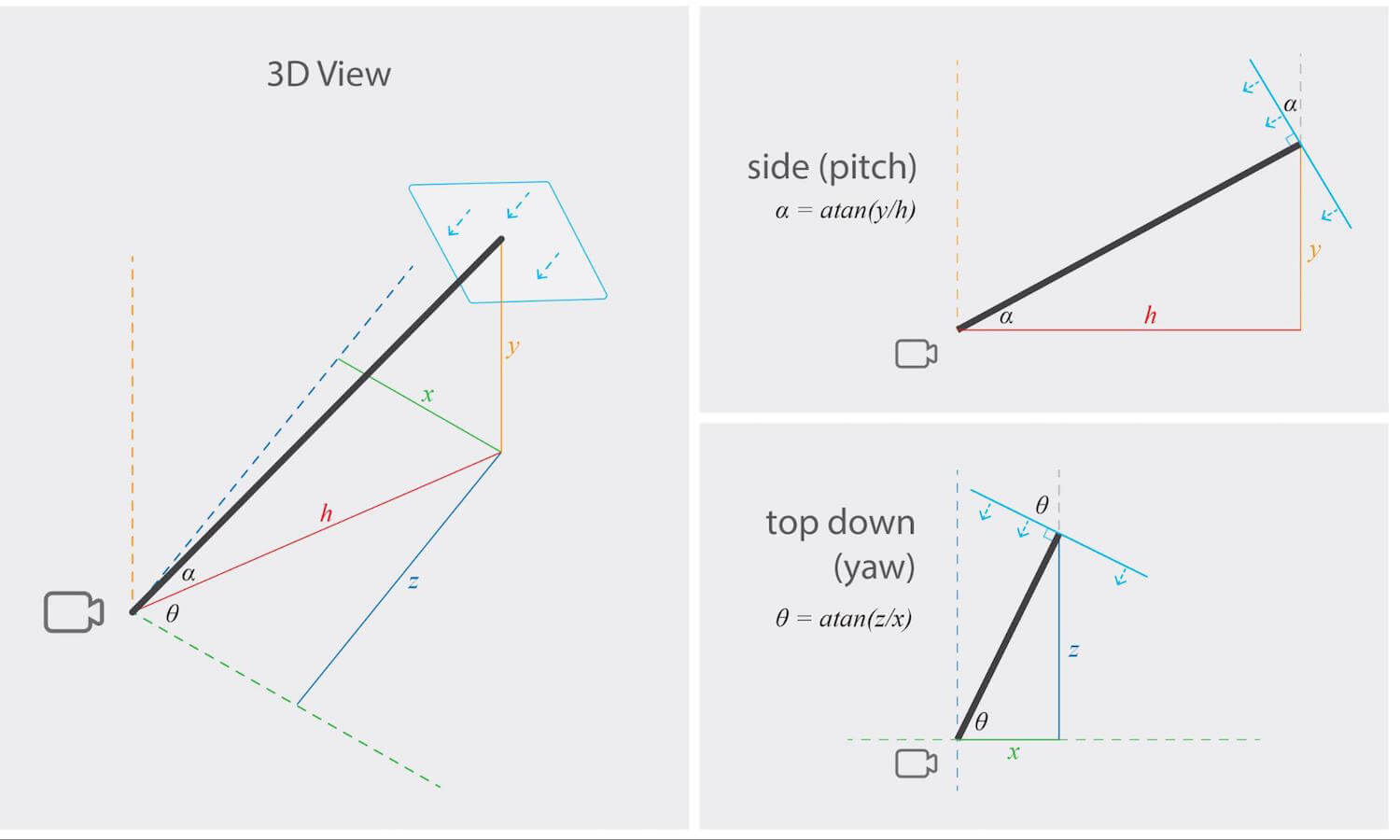
We wanted to rotate tooltips to face the user, so that the tooltip text would be easier to see. In order to achieve this, we had to work with the interior’s different coordinate system, due to the sphere being rotated to the front of the car each time. The text box with the vehicle details for the Tesla model (including price, status, year, etc.) was distorted because the user was moving their field of view, making it harder to read. When we created the text box, it faced the positive x direction, and not the origin, which distorted the writing within the text box. To fix this, we needed to work with two rotations: one for the horizontal y-axis (yaw) so that the text faces the user, and the other (pitch) so that it would face downward.
Resolution
For our set-up, the camera was located at the origin, and the text box was a plane. We calculated the adjustment of the surface of the plane to be perpendicular to the camera. The diagrams below illustrate the calculations we made to determine which angles we needed to rotate the camera:
Note: Even if you rotate the camera, the tooltips are relative to the UV mapping, so it doesn’t matter if you rotate the camera.
UV mapping is the 3D modelling process of projecting a 2D image to a 3D model’s surface for texture mapping. This makes a 2D object appear 3D.
We also had to work with the following debugged coordinate system, because the tooltips were relative to the UV mapping:
  To find UV coordinates:
U = X-coord / ImageWidth
V = Y-coord / ImageHeight
We then used a UVMapper class to convert the UV coordinates to x, y, z coordinates:
public class UVMapper {
  final static private float PADDING = 0.8f;

  public static Coord3D get3DCoord(double u, double v, int radius) {
    double phi0, cosPhi0, sinPhi0, theta0, cosTheta0, sinTheta0, x, y, z;

    phi0 = v * Math.PI;

    cosPhi0 = Math.cos(phi0);
    sinPhi0 = Math.sin(phi0);

    theta0 = u * 2 * Math.PI;
    cosTheta0 = Math.cos(theta0);
    sinTheta0 = Math.sin(theta0);

    x = sinPhi0 * cosTheta0 * radius;
    y = cosPhi0 * radius;
    z = sinPhi0 * sinTheta0 * radius;
      /*** The line above converted the UV coordinates to spherical coordinates ***/
      /*** The lines below offset the tooltips from the environment sphere ***/
    double newY = y - CarInteriorScene.CAM_HEIGHT;
    double ratio = radius * (1 - PADDING) / Math.sqrt(x * x + newY * newY + z * z);

    return new Coord3D((float) (x * (1 - ratio)), (float) (y - newY * ratio), (float) (z * (1 - ratio)));
  }
}
private void rotateToFaceCamera() {
double rotationYaw = 0;
if (posZ < 0 && posX = 0 && posX = 0 && posX >= 0) {
// Third quadrant
rotationYaw = Math.toDegrees(Math.atan(posZ / posX));
rotationYaw = 270 - rotationYaw;
}
else if (posZ = 0) {
// Fourth quadrant
rotationYaw = Math.toDegrees(Math.atan(-posZ / posX));
rotationYaw = 270 + rotationYaw;
}
//…The following one-liner can also replace the code block above, which we discovered later on in development. The benefit of using this one-liner in particular is that it’s simpler and avoids the “division by 0” case:
rotationYaw = Math.toDegrees(Math.atan2(-posX, -posZ));
Coordinate Systems
The 2D Cartesian coordinates system is used to create a 2D effect. However, 3D drawing must use a 3D coordinate system, with the additional coordinate of z, which describes depth (i.e. how far into or out of the screen an object is drawn). Creators who are familiar with the 2D coordinates system shouldn’t have much difficulty transitioning to 3D coordinates.
There are two negatives in the arguments of atan2 because of the coordinates system. The camera is facing in the direction of the negative x-axis; on its right is the negative z-axis, and above is the positive y-axis, shown in the drawing. In the code block above, the method atan is used to find the angle between the camera ray and the vertical, while atan2 is used to find the angle between the camera ray and the horizontal.
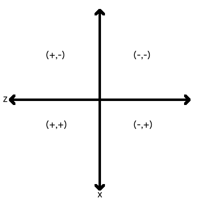
We used this calculation to find the relationship for the reversed arguments for atan2:
When a GVRSceneObject is loaded into the scene, the default position is with the z-axis with respect to the scope. For atan2 to work, both parameters need a negative sign.
Therefore, to rotate the tooltips correctly, we entered negative arguments, so that the interior’s front-right quadrant would be the duo-negative quadrant of x and z. To aid future development, the scene should not have been rotated to compensate for the incompatible scene and camera orientation. Instead, the camera should have been rotated 90 degrees, thus setting the interior’s front-right quadrant to be the duo-positive quadrant of x and z, making it very intuitive for other developers when they’re adding more objects to the scene.
 //…
  double hyp = Math.sqrt(posX * posX + posZ * posZ);
  double rotationPitch = Math.toDegrees(Math.atan2(posY, hyp));

  //rotate by x-axis
  getTransform().setRotationByAxis((float) rotationPitch, 1, 0, 0);
  //rotate by y-axis
  getTransform().rotateByAxis((float) rotationYaw, 0, 1, 0);
}
atan2 is part of the Java Math class.
A Promising Future For VR
As costs begin to decrease and components become more affordable, more VR content is being developed for users worldwide. VR has the power to show the user, rather than describe an experience to them, which is what makes VR a powerful medium that is changing the entertainment industry.
Implementing Gear 360’s two lenses was crucial for us to smoothly stitch together the images, which helped to create a more immersive VR experience. With new technologies such as the 360 camera, the future of VR holds a lot of promise for users and software developers worldwide. With a thorough understanding of the framework, proper optimization and frequent testing, you’ll be able to achieve a truly immersive VR environment. We hope that, from this, you’ll be able to avoid some of the pitfalls we encountered and will be able to create a seamless VR experience that your users will love.
Our project’s team: