Building Shaders With Babylon.js

Email Newsletter
Weekly tips on front-end & UX.
Trusted by 182,000+ folks.

 Celebrating 10 million developers
 Custom Web Forms for Angular, React, & Vue. Your backend.


Shaders are a key concept if you want to unleash the raw power of your GPU. I will help you understand how they work and even experiment with their inner power in an easy way, thanks to Babylon.js.
How Does It Work?
Before experimenting, we must see how things work internally.
When dealing with hardware-accelerated 3D, you will have to deal with two CPUs: the main CPU and the GPU. The GPU is a kind of extremely specialized CPU.
The GPU is a state machine that you set up using the CPU. For instance, the CPU will configure the GPU to render lines instead of triangles; it will define whether transparency is on; and so on.
Once all of the states are set, the CPU can define what to render: the geometry.
The geometry is composed of:
- a list of points that are called vertices and stored in an array called vertex buffer,
- a list of indexes that define the faces (or triangles) stored in an array named index buffer.
The final step for the CPU is to define how to render the geometry; for this task, the CPU will define shaders in the GPU. Shaders are pieces of code that the GPU will execute for each of the vertices and pixels it has to render. (A vertex — or vertices when there are several of them — is a “point” in 3D).
There are two kinds of shaders: vertex shaders and pixel (or fragment) shaders.
Graphics Pipeline
Before digging into shaders, let’s step back. To render pixels, the GPU will take the geometry defined by the CPU and will do the following:
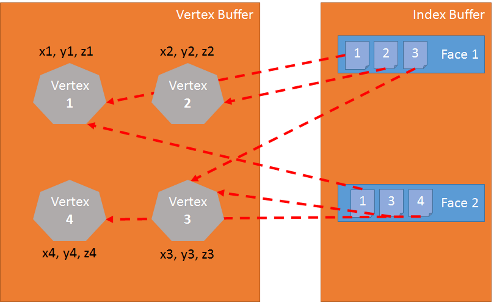
- Using the index buffer, three vertices are gathered to define a triangle.
- Index buffer contains a list of vertex indexes. This means that each entry in the index buffer is the number of a vertex in the vertex buffer.
- This is really useful to avoid duplicating vertices.
For instance, the following index buffer is a list of two faces: [1 2 3 1 3 4]. The first face contains vertex 1, vertex 2 and vertex 3. The second face contains vertex 1, vertex 3 and vertex 4. So, there are four vertices in this geometry:
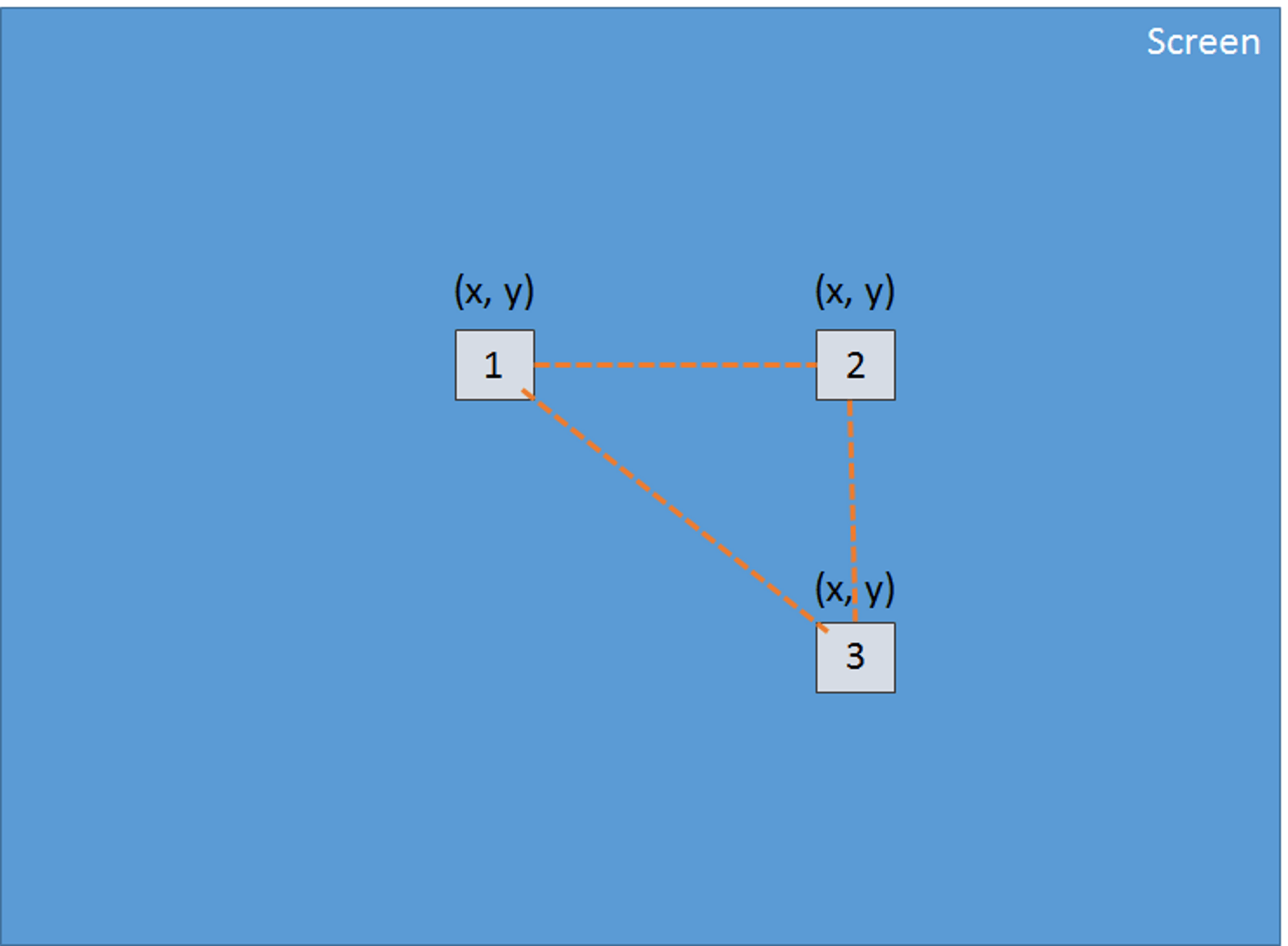
The vertex shader is applied to each vertex of the triangle. The primary goal of the vertex shader is to produce a pixel for each vertex (the projection on the 2D screen of the 3D vertex):
Using these three pixels (which define a 2D triangle on the screen), the GPU will interpolate all values attached to the pixel (at least their positions), and the pixel shader will be applied to every pixel included in the 2D triangle in order to generate a color for every pixel:
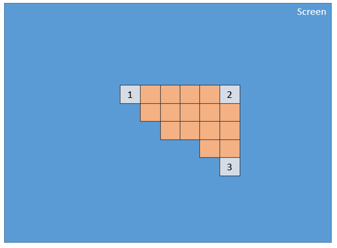
This process is done for every face defined by the index buffer.
Obviously, due to its parallel nature, the GPU is able to process this step for a lot of faces simultaneously and achieve really good performance.
GLSL
We have just seen that to render triangles, the GPU needs two shaders: the vertex shader and the pixel shader. These shaders are written in a language named Graphics Library Shader Language (GLSL). It looks like C.
Here is a sample of a common vertex shader:
precision highp float;

// Attributes
attribute vec3 position;
attribute vec2 uv;

// Uniforms
uniform mat4 worldViewProjection;

// Varying
varying vec2 vUV;

void main(void) {
    gl_Position = worldViewProjection * vec4(position, 1.0);

    vUV = uv;
}
Vertex Shader Structure
A vertex shader contains the following:
- Attributes. An attribute defines a portion of a vertex. By default, a vertex should at least contain a position (a
vector3:x, y, z). However, as a developer, you can decide to add more information. For instance, in the former shader, there is avector2nameduv(i.e. texture coordinates that allow you to apply a 2D texture to a 3D object). - Uniforms. A uniform is a variable used by the shader and defined by the CPU. The only uniform we have here is a matrix used to project the position of the vertex (x, y, z) to the screen (x, y).
- Varying. Varying variables are values created by the vertex shader and transmitted to the pixel shader. Here, the vertex shader will transmit a
vUV(a simple copy ofuv) value to the pixel shader. This means that a pixel is defined here with a position and texture coordinates. These values will be interpolated by the GPU and used by the pixel shader. - Main. The function named
mainis the code executed by the GPU for each vertex and must at least produce a value forgl_position(the position of the current vertex on the screen).
We can see in our sample that the vertex shader is pretty simple. It generates a system variable (starting with gl_) named gl_position to define the position of the associated pixel, and it sets a varying variable called vUV.
The Voodoo Behind Matrices
The thing about our shader is that we have a matrix named worldViewProjection, and we use this matrix to project the vertex position to the gl_position variable. That is cool, but how do we get the value of this matrix? It is a uniform, so we have to define it on the CPU side (using JavaScript).
This is one of the complex parts of doing 3D. You must understand complex math (or you will have to use a 3D engine such as Babylon.js, which we will see later).
The worldViewProjection matrix is the combination of three different matrices:
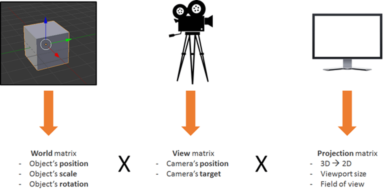
Using the resulting matrix enables us to transform 3D vertices to 2D pixels, while taking into account the point of view and everything related to the position, scale and rotation of the current object.
This is your responsibility as a 3D developer: to create and keep this matrix up to date.
Back To The Shaders
Once the vertex shader is executed on every vertex (three times, then), we will have three pixels with the correct gl_position and a vUV value. The GPU is going to interpolate these values on every pixel contained in the triangle produced with these pixels.
Then, for each pixel, it will execute the pixel shader:
precision highp float;
varying vec2 vUV;
uniform sampler2D textureSampler;

void main(void) {
    gl_FragColor = texture2D(textureSampler, vUV);
}
Pixel (Or Fragment) Shader Structure
The structure of a pixel shader is similar to that of a vertex shader:
- Varying. Varying variables are value created by the vertex shader and transmitted to the pixel shader. Here, the pixel shader will receive a
vUVvalue from the vertex shader. - Uniforms. A uniform is a variable used by the shader and defined by the CPU. The only uniform we have here is a sampler, which is a tool used to read texture colors.
- Main. The function named
mainis the code executed by the GPU for each pixel and that must at least produce a value forgl_FragColor(i.e. the color of the current pixel).
This pixel shader is fairly simple: It reads the color from the texture using texture coordinates from the vertex shader (which, in turn, gets it from the vertex).
The problem is that when shaders are developed, you are only halfway there, because you then have to deal with a lot of WebGL code. Indeed, WebGL is really powerful but also really low-level, and you have to do everything yourself, from creating the buffers to defining vertex structures. You also have to do all of the math, set all of the states, handle texture-loading, and so on.
Too Hard? BABYLON.ShaderMaterial To The Rescue
I know what you’re thinking: “Shaders are really cool, but I do not want to bother with WebGL’s internal plumbing or even with the math.”
And you are right! This is a perfectly legitimate question, and that is exactly why I created Babylon.js!
To use Babylon.js, you first need a simple web page:
<!DOCTYPE html>
<html>
<head>
    <title>Babylon.js</title>
    <script src="Babylon.js"></script>

    <script type="application/vertexShader" id="vertexShaderCode">
        precision highp float;

        // Attributes
        attribute vec3 position;
        attribute vec2 uv;

        // Uniforms
        uniform mat4 worldViewProjection;

        // Normal
        varying vec2 vUV;

        void main(void) {
        gl_Position = worldViewProjection * vec4(position, 1.0);

        vUV = uv;
        }
    </script>

    <script type="application/fragmentShader" id="fragmentShaderCode">
        precision highp float;
        varying vec2 vUV;

        uniform sampler2D textureSampler;

        void main(void) {
        gl_FragColor = texture2D(textureSampler, vUV);
        }
    </script>

    <script src="index.js"></script>
    <style>
        html, body {
            width: 100%;
            height: 100%;
            padding: 0;
            margin: 0;
            overflow: hidden;
            margin: 0px;
            overflow: hidden;
        }

        #renderCanvas {
            width: 100%;
            height: 100%;
            touch-action: none;
            -ms-touch-action: none;
        }
    </style>
</head>
<body>
    <canvas id="renderCanvas"></canvas>
</body>
</html>
You’ll notice that shaders are defined by <script> tags. With Babylon.js, you can also define them in separate files (.fx files).
Finally, the main JavaScript code is this:
"use strict";
document.addEventListener("DOMContentLoaded", startGame, false);

function startGame() {
    if (BABYLON.Engine.isSupported()) {
        var canvas = document.getElementById("renderCanvas");
        var engine = new BABYLON.Engine(canvas, false);
        var scene = new BABYLON.Scene(engine);
        var camera = new BABYLON.ArcRotateCamera("Camera", 0, Math.PI / 2, 10, BABYLON.Vector3.Zero(), scene);

        camera.attachControl(canvas);

        // Creating sphere
        var sphere = BABYLON.Mesh.CreateSphere("Sphere", 16, 5, scene);

        var amigaMaterial = new BABYLON.ShaderMaterial("amiga", scene, {
            vertexElement: "vertexShaderCode",
            fragmentElement: "fragmentShaderCode",
        },
        {
            attributes: ["position", "uv"],
            uniforms: ["worldViewProjection"]
        });
        amigaMaterial.setTexture("textureSampler", new BABYLON.Texture("amiga.jpg", scene));

        sphere.material = amigaMaterial;

        engine.runRenderLoop(function () {
            sphere.rotation.y += 0.05;
            scene.render();
        });
    }
};
You can see that I use BABYLON.ShaderMaterial to get rid of the burden of compiling, linking and handling shaders.
When you create BABYLON.ShaderMaterial, you have to specify the DOM element used to store the shaders or the base name of the files where the shaders are. If you choose to use files, you must create a file for each shader and use the following pattern: basename.vertex.fx and basename.fragment.fx. Then, you will have to create the material like this:
var cloudMaterial = new BABYLON.ShaderMaterial("cloud", scene, "./myShader",
        {
            attributes: ["position", "uv"],
            uniforms: ["worldViewProjection"]
        });
You must also specify the names of attributes and uniforms that you use.
Then, you can directly set the values of your uniforms and samplers using setTexture, setFloat, setFloats, setColor3, setColor4, setVector2, setVector3, setVector4, setMatrix functions.
Pretty simple, right?
And do you remember the previous worldViewProjection matrix, using Babylon.js and BABYLON.ShaderMaterial. You just don’t have to worry about it! BABYLON.ShaderMaterial will automatically compute it for you because you’ll declare it in the list of uniforms.
BABYLON.ShaderMaterial can also handle the following matrices for you:
world,view,projection,worldView,worldViewProjection.
No need for math anymore. For instance, each time you execute sphere.rotation.y += 0.05, the world matrix of the sphere will be generated for you and transmitted to the GPU.
Create Your Own Shader (CYOS)
Now, let’s go bigger and create a page where you can dynamically create your own shaders and see the result immediately. This page is going to use the same code that we discussed previously and is going to use the BABYLON.ShaderMaterial object to compile and execute shaders that you will create.
I used the ACE code editor for Create Your Own Shader (CYOS). It is an incredible code editor, with syntax highlighting. Feel free to have a look at it.
Using the first combo box, you will be able to select predefined shaders. We will see each of them right after.
You can also change the mesh (i.e. the 3D object) used to preview your shaders using the second combo box.
The compile button is used to create a new BABYLON.ShaderMaterial from your shaders. The code used by this button is as follows:
// Compile
shaderMaterial = new BABYLON.ShaderMaterial("shader", scene, {
vertexElement: "vertexShaderCode",
fragmentElement: "fragmentShaderCode",
},
{
attributes: ["position", "normal", "uv"],
uniforms: ["world", "worldView", "worldViewProjection"]
});
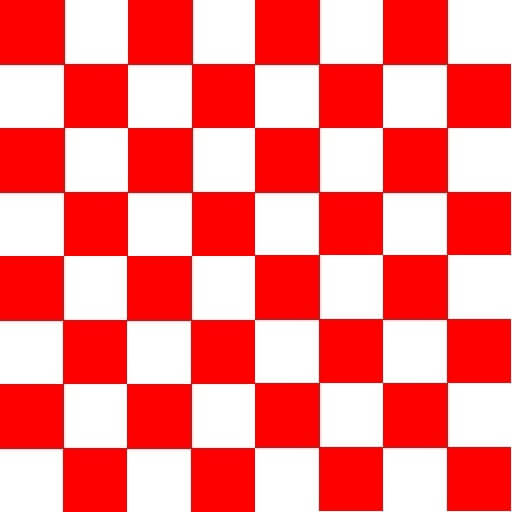
var refTexture = new BABYLON.Texture("ref.jpg", scene);
refTexture.wrapU = BABYLON.Texture.CLAMP_ADDRESSMODE;
refTexture.wrapV = BABYLON.Texture.CLAMP_ADDRESSMODE;
var amigaTexture = new BABYLON.Texture("amiga.jpg", scene);
shaderMaterial.setTexture("textureSampler", amigaTexture);
shaderMaterial.setTexture("refSampler", refTexture);
shaderMaterial.setFloat("time", 0);
shaderMaterial.setVector3("cameraPosition", BABYLON.Vector3.Zero());
shaderMaterial.backFaceCulling = false;
mesh.material = shaderMaterial;
Incredibly simple, right? The material is ready to send you three pre-computed matrices (world, worldView and worldViewProjection). Vertices will come with position, normal and texture coordinates. Two textures are also already loaded for you:
amiga.jpg (View large version)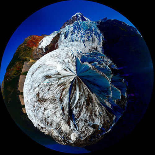
ref.jpg (View large version)Finally, the renderLoop is where I update two convenient uniforms:
- One is called
timeand gets some funny animations. - The other is called
cameraPosition, which gets the position of the camera into your shaders (useful for lighting equations).
engine.runRenderLoop(function () {
    mesh.rotation.y += 0.001;

    if (shaderMaterial) {
        shaderMaterial.setFloat("time", time);
        time += 0.02;

        shaderMaterial.setVector3("cameraPosition", camera.position);
    }

    scene.render();
});
Basic Shader
Let’s start with the very first shader defined in CYOS: the basic shader.
We already know this shader. It computes the gl_position and uses texture coordinates to fetch a color for every pixel.
To compute the pixel position, we just need the worldViewProjection matrix and the vertex’s position:
precision highp float;

// Attributes
attribute vec3 position;
attribute vec2 uv;

// Uniforms
uniform mat4 worldViewProjection;

// Varying
varying vec2 vUV;

void main(void) {
    gl_Position = worldViewProjection * vec4(position, 1.0);

    vUV = uv;
}
Texture coordinates (uv) are transmitted unmodified to the pixel shader.
Please note that we need to add precision mediump float on the first line for both the vertex and pixel shaders because Chrome requires it. It specifies that, for better performance, we do not use full precision floating values.
The pixel shader is even simpler, because we just need to use texture coordinates and fetch a texture color:
precision highp float;

varying vec2 vUV;

uniform sampler2D textureSampler;

void main(void) {
    gl_FragColor = texture2D(textureSampler, vUV);
}
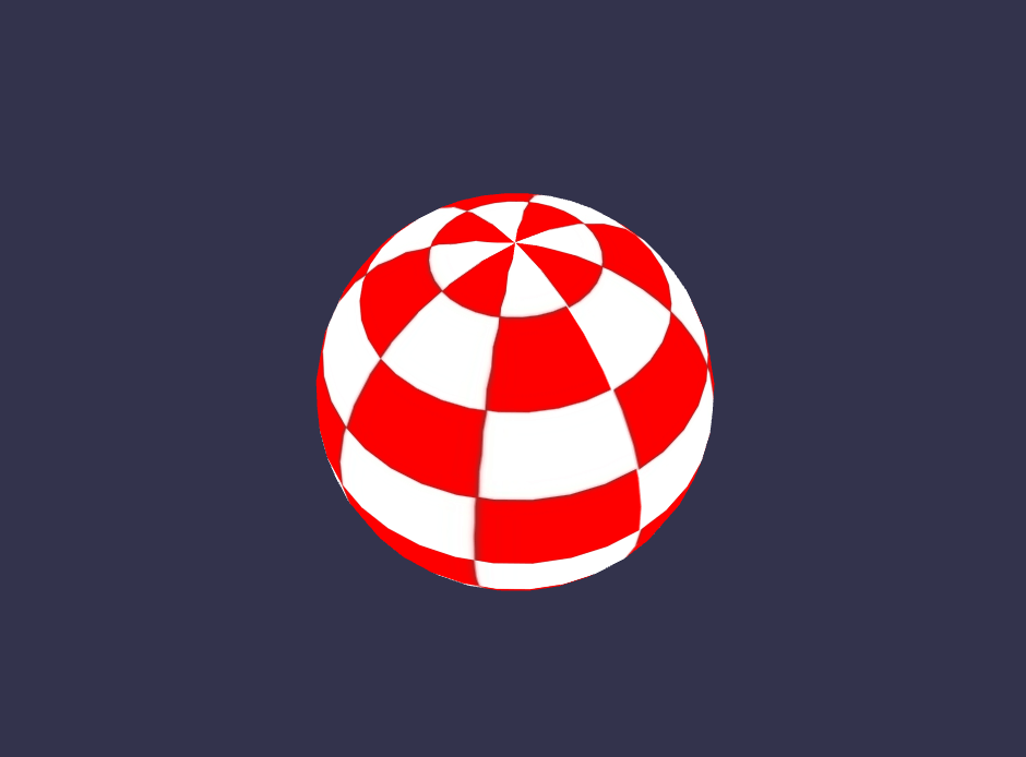
We previously saw that the textureSampler uniform is filled with the amiga texture. So, the result is the following:
Black And White Shader
Let’s continue with a new shader: the black and white shader. The goal of this shader is to use the previous one but with a black and white-only rendering mode.
To do so, we can keep the same vertex shader. The pixel shader will be slightly modified.
The first option we have is to take only one component, such as the green one:
precision highp float;

varying vec2 vUV;

uniform sampler2D textureSampler;

void main(void) {
    gl_FragColor = vec4(texture2D(textureSampler, vUV).ggg, 1.0);
}
As you can see, instead of using .rgb (this operation is called a swizzle), we’ve used .ggg.
But if we want a really accurate black and white effect, then computing the luminance (which takes into account all components) would be better:
precision highp float;

varying vec2 vUV;

uniform sampler2D textureSampler;

void main(void) {
    float luminance = dot(texture2D(textureSampler, vUV).rgb, vec3(0.3, 0.59, 0.11));
    gl_FragColor = vec4(luminance, luminance, luminance, 1.0);
}
The dot operation (or dot product) is computed like this: result = v0.x * v1.x + v0.y * v1.y + v0.z * v1.z.
So, in our case, luminance = r * 0.3 + g * 0.59 + b * 0.11. (These values are based on the fact that the human eye is more sensitive to green.)
Sounds cool, doesn’t it?

Cell-Shading Shader
Let’s move to a more complex shader: the cell-shading shader.
This one will require us to get the vertex’s normal and the vertex’s position into the pixel shader. So, the vertex shader will look like this:
precision highp float;

// Attributes
attribute vec3 position;
attribute vec3 normal;
attribute vec2 uv;

// Uniforms
uniform mat4 world;
uniform mat4 worldViewProjection;

// Varying
varying vec3 vPositionW;
varying vec3 vNormalW;
varying vec2 vUV;

void main(void) {
    vec4 outPosition = worldViewProjection * vec4(position, 1.0);
    gl_Position = outPosition;

    vPositionW = vec3(world * vec4(position, 1.0));
    vNormalW = normalize(vec3(world * vec4(normal, 0.0)));

    vUV = uv;
}
Please note that we also use the world matrix because position and normal are stored without any transformation, and we must apply the world matrix to take into account the object’s rotation.
The pixel shader is as follows:
precision highp float;

// Lights
varying vec3 vPositionW;
varying vec3 vNormalW;
varying vec2 vUV;

// Refs
uniform sampler2D textureSampler;

void main(void) {
    float ToonThresholds[4];
    ToonThresholds[0] = 0.95;
    ToonThresholds[1] = 0.5;
    ToonThresholds[2] = 0.2;
    ToonThresholds[3] = 0.03;

    float ToonBrightnessLevels[5];
    ToonBrightnessLevels[0] = 1.0;
    ToonBrightnessLevels[1] = 0.8;
    ToonBrightnessLevels[2] = 0.6;
    ToonBrightnessLevels[3] = 0.35;
    ToonBrightnessLevels[4] = 0.2;

    vec3 vLightPosition = vec3(0, 20, 10);

    // Light
    vec3 lightVectorW = normalize(vLightPosition - vPositionW);

    // diffuse
    float ndl = max(0., dot(vNormalW, lightVectorW));

    vec3 color = texture2D(textureSampler, vUV).rgb;

    if (ndl > ToonThresholds[0])
    {
        color *= ToonBrightnessLevels[0];
    }
    else if (ndl > ToonThresholds[1])
    {
        color *= ToonBrightnessLevels[1];
    }
    else if (ndl > ToonThresholds[2])
    {
        color *= ToonBrightnessLevels[2];
    }
    else if (ndl > ToonThresholds[3])
    {
        color *= ToonBrightnessLevels[3];
    }
    else
    {
        color *= ToonBrightnessLevels[4];
    }

    gl_FragColor = vec4(color, 1.);
}
The goal of this shader is to simulate light, and instead of computing smooth shading, we will apply the light according to specific brightness thresholds. For instance, if the light intensity is between 1 (maximum) and 0.95, the color of the object (fetched from the texture) would be applied directly. If the intensity is between 0.95 and 0.5, the color would be attenuated by a factor of 0.8. And so on.
There are mainly four steps in this shader.
First, we declare thresholds and levels constants.
Then, we compute the lighting using the Phong equation (we’ll consider that the light is not moving):
vec3 vLightPosition = vec3(0, 20, 10);

// Light
vec3 lightVectorW = normalize(vLightPosition - vPositionW);

// diffuse
float ndl = max(0., dot(vNormalW, lightVectorW));
The intensity of light per pixel depends on the angle between the normal and light direction.
Then, we get the texture color for the pixel.
Finally, we check the threshold and apply the level to the color.
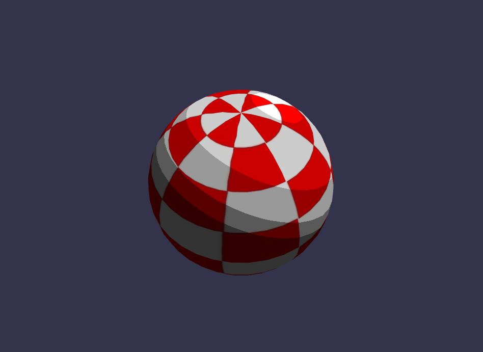
The result looks like a cartoon object:
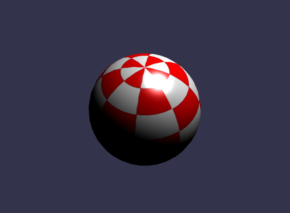
Phong Shader
We used a portion of the Phong equation in the previous shader. Let’s use it completely now.
The vertex shader is clearly simple here because everything will be done in the pixel shader:
precision highp float;

// Attributes
attribute vec3 position;
attribute vec3 normal;
attribute vec2 uv;

// Uniforms
uniform mat4 worldViewProjection;

// Varying
varying vec3 vPosition;
varying vec3 vNormal;
varying vec2 vUV;

void main(void) {
    vec4 outPosition = worldViewProjection * vec4(position, 1.0);
    gl_Position = outPosition;

    vUV = uv;
    vPosition = position;
    vNormal = normal;
}
According to the equation, we must compute the “diffuse” and “specular” parts using light direction and vertex’s normal:
precision highp float;

// Varying
varying vec3 vPosition;
varying vec3 vNormal;
varying vec2 vUV;

// Uniforms
uniform mat4 world;

// Refs
uniform vec3 cameraPosition;
uniform sampler2D textureSampler;

void main(void) {
    vec3 vLightPosition = vec3(0, 20, 10);

    // World values
    vec3 vPositionW = vec3(world * vec4(vPosition, 1.0));
    vec3 vNormalW = normalize(vec3(world * vec4(vNormal, 0.0)));
    vec3 viewDirectionW = normalize(cameraPosition - vPositionW);

    // Light
    vec3 lightVectorW = normalize(vLightPosition - vPositionW);
    vec3 color = texture2D(textureSampler, vUV).rgb;

    // diffuse
    float ndl = max(0., dot(vNormalW, lightVectorW));

    // Specular
    vec3 angleW = normalize(viewDirectionW + lightVectorW);
    float specComp = max(0., dot(vNormalW, angleW));
    specComp = pow(specComp, max(1., 64.)) * 2.;

    gl_FragColor = vec4(color * ndl + vec3(specComp), 1.);
}
We already used the diffuse part in the previous shader, so here we just need to add the specular part. You can find more information about Phong shading on Wikipedia.
The result of our sphere:
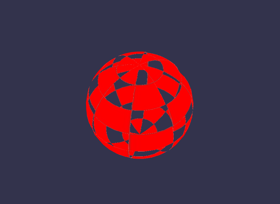
Discard Shader
For the discard shader, I would like to introduce a new concept: the discard keyword.
This shader discards every non-red pixel and creates the illusion of a dug object.
The vertex shader is the same used by the basic shader:
precision highp float;

// Attributes
attribute vec3 position;
attribute vec3 normal;
attribute vec2 uv;

// Uniforms
uniform mat4 worldViewProjection;

// Varying
varying vec2 vUV;

void main(void) {
    gl_Position = worldViewProjection * vec4(position, 1.0);

    vUV = uv;
}
The pixel shader on its side will have to test the color and use discard when, for instance, the green component is too high:
precision highp float;

varying vec2 vUV;

// Refs
uniform sampler2D textureSampler;

void main(void) {
    vec3 color = texture2D(textureSampler, vUV).rgb;

    if (color.g > 0.5) {
        discard;
    }

    gl_FragColor = vec4(color, 1.);
}
The result is a little funny:
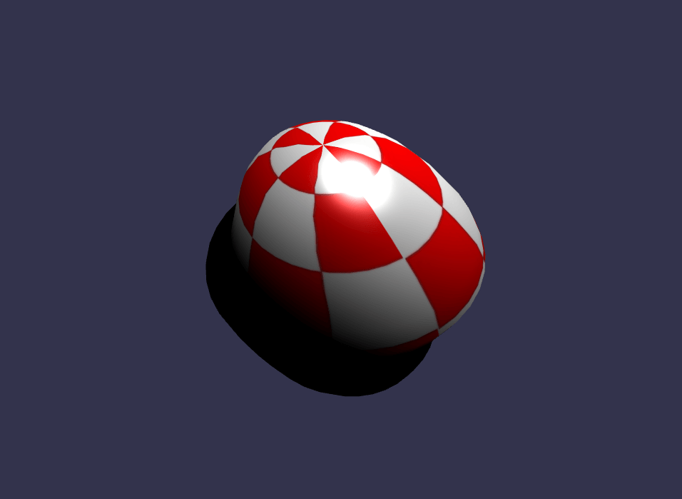
Wave Shader
We’ve played a lot with pixel shader, but I also want to let you know that we can do a lot of thing with vertex shaders.
For the wave shader, we will reuse the Phong pixel shader.
The vertex shader will use the uniform named time to get some animated values. Using this uniform, the shader will generate a wave with the vertices’ positions:
precision highp float;

// Attributes
attribute vec3 position;
attribute vec3 normal;
attribute vec2 uv;

// Uniforms
uniform mat4 worldViewProjection;
uniform float time;

// Varying
varying vec3 vPosition;
varying vec3 vNormal;
varying vec2 vUV;

void main(void) {
    vec3 v = position;
    v.x += sin(2.0 * position.y + (time)) * 0.5;

    gl_Position = worldViewProjection * vec4(v, 1.0);

    vPosition = position;
    vNormal = normal;
    vUV = uv;
}
A sinus is applied to position.y, and the result is as follows:
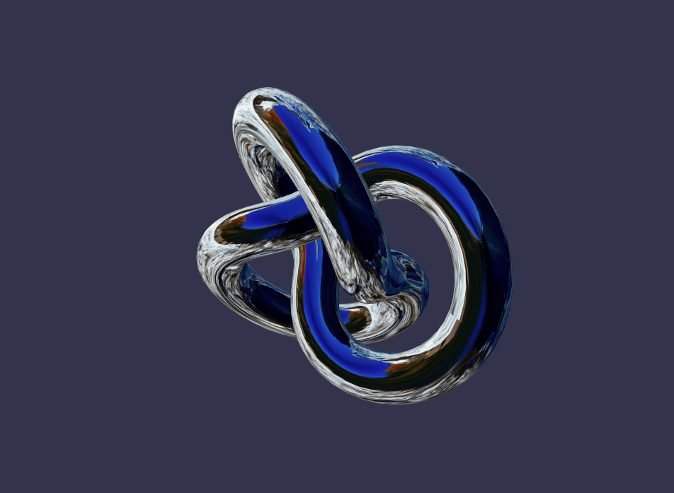
Spherical Environment Mapping
This one was largely inspired by the article “Creating a Spherical Reflection/Environment Mapping Shader.” I’ll let you read that excellent article and play with the associated shader.
Fresnel Shader
I would like to conclude this article with my favorite: the Fresnel shader.
This shader is used to apply a different intensity according to the angle between the view direction and the vertex’s normal.
The vertex shader is the same one used by the cell-shading shader, and we can easily compute the Fresnel term in our pixel shader (because we have the normal and the camera’s position, which can be used to evaluate the view direction):
precision highp float;

// Lights
varying vec3 vPositionW;
varying vec3 vNormalW;

// Refs
uniform vec3 cameraPosition;
uniform sampler2D textureSampler;

void main(void) {
    vec3 color = vec3(1., 1., 1.);
    vec3 viewDirectionW = normalize(cameraPosition - vPositionW);

    // Fresnel
    float fresnelTerm = dot(viewDirectionW, vNormalW);
    fresnelTerm = clamp(1.0 - fresnelTerm, 0., 1.);

    gl_FragColor = vec4(color * fresnelTerm, 1.);
}
Your Shader?
You are now more prepared to create your own shader. Feel free to post to the Babylon.js forum to share your experiments!
If you want to go further, here are some useful links:
- Babylon.js, official website
- Babylon.js, GitHub repository
- Babylon.js forum, HTML5 Game Devs
- Create Your Own Shader (CYOS), Babylon.js
- OpenGL Shading Language,” Wikipedia
- OpenGL Shading Language, documentation
Further Reading
- Building A Cross-Platform WebGL Game With Babylon.js
- Using The Gamepad API In Web Games
- Introduction To Polygonal Modeling And Three.js
- How To Create A Responsive 8-Bit Drum Machine