How To Prototype IoT Experiences: Configuring The Software (Part 2)

Email Newsletter
Weekly tips on front-end & UX.
Trusted by 182,000+ folks.
 Custom Web Forms for Angular, React, & Vue. Your backend.
 Celebrating 10 million developers


In the first article of this series, we walked through how to put together the hardware board and all of its additional components into a single rig. I also gave you a glimpse of the decision-making process behind the selection of the board.
In this second (and last) article of the series, we will go over the code that will drive the sensor and the communication to the cloud. Additionally, we will configure a custom dashboard on Adafruit IO, so that we can visualize our data in real time.
This article assumes you are using a Mac, but much of the content carries over to Windows systems as well. For the coding sections, we will be using Arduino’s integrated development environment (IDE) and the C/C++ programming language. There are different ways to get to the same result, so pick the board and programming language that you are most familiar with. We have a lot of ground to cover, so let’s begin!
Preparing The Software Environment
Some Quick Definitions
Similar to part 1, I am going to introduce some terms, which will be used throughout this article. Many of these will make more sense as you progress through the sections, I promise!
- Adafruit IO. This is the web front end used to create and view dashboards of widgets (called blocks), as well as to illustrate data gathered from rigs and passed to the Adafruit cloud servers via the MQTT protocol.
- block. This is a single user interface (UI) widget in an Adafruit IO dashboard. A widget can be used to input a user action or to output data.
- feed. An MQTT construct, this is an inbound or outbound connection to a server (MQTT broker) passing data from a hardware rig. Feeds can be assigned to Adafruit IO dashboard blocks.
- MQTT. This is a low-bandwidth protocol for passing data back and forth between a server and hardware rig.
Criteria
My approach for selecting a cloud platform was much less systematic than my criteria for selecting a board. Initially, I considered OpenHAB and a few other platforms, but ultimately voted against all of them due to the amount of setup needed up front — for example, getting MQTT (the communication protocol between the board and the cloud) to run would have been a pain. This could have presented even more opportunities to introduce errors.
Picking the HUZZAH ESP8266 naturally led me to explore Adafruit IO. However, this choice was not made without a few criteria:
- integrated board and cloud experience,
- minimal need for configuring connectivity to the cloud,
- ability to customize the UI to view data,
- a responsive UI (viewable on different devices).
When you are deciding on a cloud platform for your project, a good place to start is Postscapes’ “IoT Cloud Platform Landscape.” Keep in mind that the list has both open-source and commercial offerings, but it is not by any means complete. For example, both Adafruit IO and OpenHab are not included.
Using custom code to establish connections between a hardware rig and a remote server will get you a long way in terms of flexibility and performance. There are many ways to do this, but the goal of this second article is to introduce you to a method that will get you up and running quickly!
Note: Keep in mind that your needs will vary. Because there is no single way to skin the proverbial cat, pick something that works best for your setup and budget!
Getting Started
Before you add any of the code, some housekeeping items are needed. You will need to get additional software to make your setup work. I will cover each one in detail below, but here is a quick breakdown of what each one does.
Software Components
- Arduino IDE (free, but donations accepted) This is a development environment where you can enter your code, manage code libraries and change the board’s settings.
- ESP8266 support (free) This is a JSON file with a series of key-value pairs outlining the hardware settings for a series of boards (for example,
Name: “HUZZAH ESP8266”). - MQTT library (free) This additional code is needed to drive MQTT communication. Upon adding this library to your sketch, you can use abstractions of the code for additional functionality.
- Adafruit.io free beta account + AIO key (free) The code is only half the solution. This will help you detect data and push the data to the cloud. With the account, you can connect to the cloud and create dashboards, which will receive your data as feeds. The key authenticates you.
Arduino IDE
Start by going to the Arduino website and installing the IDE. It is available for Windows, Mac OS X and other operating systems for free. If you like it and value the organization’s effort, feel free to donate to its ongoing development.
If you are not familiar with the tool, it is worth checking out Arduino’s tutorial. It covers all aspects of the tool: how code is organized into sketches, how to upload code, how to organize libraries and many other important topics.
ESP8266 Support
HUZZAH ESP8266 is not a board supported by the IDE out of the box. Therefore, you’ll need to install a special package to provide support for all ESP8266 board variants.
On a Mac, in the application’s menu, go to “Arduino” → “Preferences.” Then:
- Under the “Settings” tab, find “Additional Board Manager URLs.”
- Type
https://arduino.esp8266.com/stable/package_esp8266com_index.jsonand hit “OK.” - Go to “Tools” → “Board” → “Board Manager” and search for
esp8266 packageby the ESP8266 community. Install it, and you should be good!
Random Nerd Tutorials has more information on steps 1 to 4.
MQTT Library
HUZZAH uses MQTT (short for Messaging Queuing Telemetry Transport), a messaging protocol, to transfer data over a Wi-Fi signal. Adafruit has implemented a library to support this protocol, including a client and server.
You can install the library using the built-in library manager:
- From top menu, click on “Sketch” → “Include Library” → “Manage Library.”
- In the popup window, search for
Adafruit MQTT Library. Make sure it is the one by Adafruit. Go ahead and install it. - Usually after a library installation, I restart the IDE to ensure there are no glitches.
Arduino has a detailed walkthrough of how to install libraries for its IDE. And Adafruit has details on the MQTT API.
The reed switch does not require a library of its own because you will read whether voltage is present (“HIGH” or a value of 1) or not (“LOW” or a value of 0) on the sensor’s “S” pin. If magnetism is present, then the two metal pieces in the glass tube will touch, thus forming a circuit and passing the voltage through.
As a side note, the ESP8266WiFi library should be installed in the Arduino IDE by default. If it is not, you can always install it like the way you installed the MQTT one. Search for the one authored by Ivan Grokhotkov.
Obtaining An Adafruit IO Account
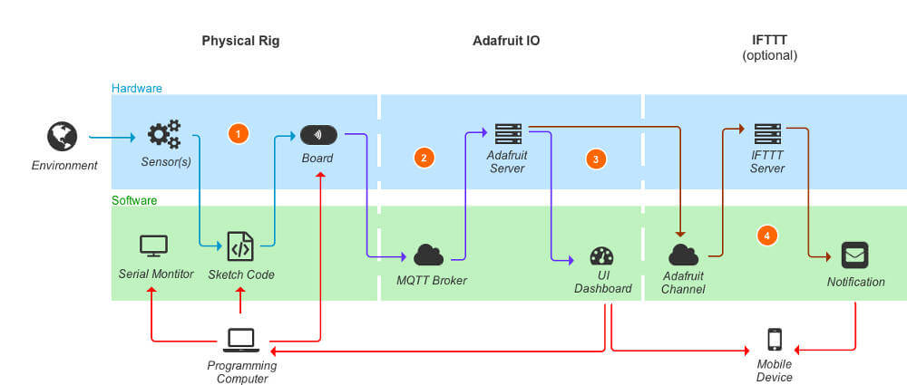
Let’s talk briefly about how data from the sensor makes it all the way to the Adafruit IO dashboard (more details on dashboards later).
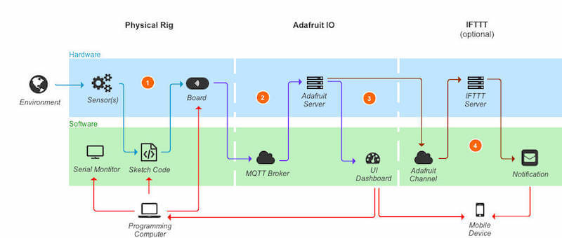
The sensor registers the information and sends it to the HUZZAH board (as seen in annotation 1 in the graphic above).
In annotation 2, the board itself opens an Internet connection over Wi-Fi to the MQTT broker, which is the server-side software component residing at https://io.adafruit.com and waiting for incoming data messages. This connection is established by confirming your identity via a specially created token (AIO key) for the website. To get a token, you need to create an account on the website. This is the focus of the current subsection.
The data is passed in the form of channels of information called feeds, which are used by MQTT. You can use prebuilt widgets called blocks (annotation 3) to create custom dashboards in Adafruit IO, which convert the data feed to visualized information.
With this background, let’s go over how to obtain the token information:
- Go to https://io.adafruit.com/ and create an account.
- You will soon receive an approval email.
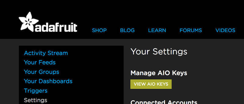
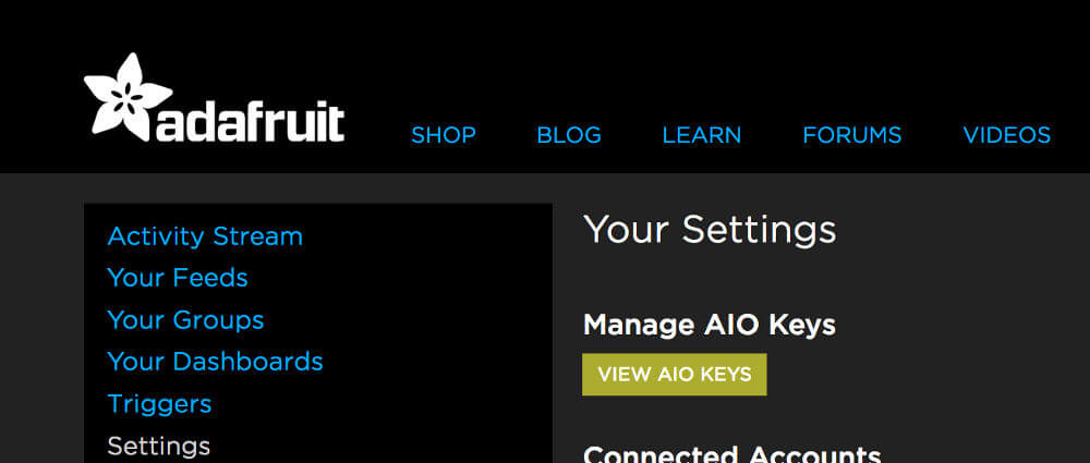
- Log in and navigate to “Settings.” There, look for “View AIO keys” (the yellow box) and click on it.
- You will see your token, which you can copy and paste in Arduino sketches.
Note: Keep that key secret because it allows you to connect to your dashboards!
Writing The Code
Code Logic
Let’s talk through the major sections of the code. The purpose of this section is not to teach you the C programming language (used in the sketch), but to explain at a high level the logic involved.
There are three main areas: variable, object and function declarations; the setup function; and the loop function. The first captures assets that you will use throughout the sketch. The second, setup, is called once and provides some up-front staging. Finally, the loop is the actual code that is executed repeatedly.
Note: You can access the full sketch code via the .ino file. You will find both the regular and secure versions of the code. The excerpts below refer to the regular code and are comment-free to reduce clutter, but the actual files are heavily annotated for your benefit.
Arduino has more information on the basics of a sketch.
Before going any further, I should say that parts of the code (for connecting to the Wi-Fi and MQTT) are written by Marc-Olivier Schwartz, a frequent contributor of tutorials on various hardware prototyping platforms. Also, most of the secure-based code file uses best practices outlined by the folks at Adafruit.
Step 1. The first step is to add all of the necessary libraries. The first one is for accessing the Wi-Fi of the board, and the next two are for sending and receiving data over MQTT.
#include <ESP8266WiFi.h>
#include <Adafruit_MQTT.h>
#include <Adafruit_MQTT_Client.h>
Step 2. Next, you can specify some parameters that will be used throughout the sketch, including Wi-Fi and Adafruit IO credentials, and the “pin 5” for the sensor data.
#define WLAN_SSID       "Your Wi-Fi network name"
#define WLAN_PASS       "Your Wi-Fi password"

#define DOOR1 5

#define AIO_SERVER      "io.adafruit.com"
#define AIO_SERVERPORT  1883
#define AIO_USERNAME    "Your Adafruit IO username"
#define AIO_KEY         "Your Adafruit IO key"
Note: Make sure to update the above with your information. The username is your username, not your registration email address!
Step 3. It is time to set up the Wi-Fi client, the MQTT client and the feed to which you want to publish data using the variables we declared above.
WiFiClient client;

Adafruit_MQTT_Client mqtt(&client, AIO_SERVER, AIO_SERVERPORT, AIO_USERNAME, AIO_KEY);

Adafruit_MQTT_Publish door1 = Adafruit_MQTT_Publish(&mqtt, AIO_USERNAME "/feeds/patio_door1");
Note: Make sure to update the feed name with the name you have chosen. The feed name can be set up once you log into Adafruit IO. I’ll cover this in detail in the next section.
Step 4. Also, call out the connect function, which checks whether an MQTT connection has been established. The entire function is detailed at the end of the sketch, with all possible error codes listed:
void connect();Step 5. During setup, you should specify that pin 5 (DOOR1) will be an input pin — that is, data will be coming from there.
Next, set up the baud rate (i.e. refresh rate) for the serial monitor, so that you can see in real time a printout of the output on the computer, which will help with troubleshooting.
As a last step, establish a Wi-Fi connection using your home Wi-Fi network, and print the assigned IP address (the address of the HUZZAH board on the network).
void setup() {

pinMode(DOOR1, INPUT);

Serial.begin(115200);
Serial.println(F("Adafruit IO"));

Serial.println();
Serial.println();
delay(10);
Serial.print(F("Connecting to "));
Serial.println(WLAN_SSID);

WiFi.begin(WLAN_SSID, WLAN_PASS);
while (WiFi.status() != WL_CONNECTED) {

delay(500);
Serial.print(F("."));

}
Serial.println();

Serial.println(F("Wi-Fi is connected!"));
Serial.println(F("IP address: "));

Serial.println(WiFi.localIP());

connect();
}
Step 6. The first part of the loop code checks whether the MQTT connection is still active, and if it is not, it reconnects:
if(! mqtt.ping(3)) {

if(! mqtt.connected())
connect();
}
Step 7. Now we have to grab the sensor data:
1means door opened (no magnetic force is present).0means door closed (a magnetic force is present).
Note: The values of 1 and 0 are not arbitrary. These are directly connected to Adafruit IO dashboard widgets called blocks, which we will cover in the next section. If you change the values here, make sure to update the appropriate block settings as well.
int door_val1;
if (digitalRead(DOOR1) == HIGH)
door_val1 = 1;
else
door_val1 = 0;
Step 8. As a last step, take the data collected and push it to the cloud via MQTT. The last line in the code below publishes a new value to MQTT every 1 second.
This assumes that opening and closing a door takes about this amount of time. It does not account for rushed entry, damage to the door or other edge cases.
if (! door1.publish(door1_val))
Serial.println(F("Failed to publish door feed!"));

else {
Serial.print("Is door opened? ");
Serial.println(door_val1);
Serial.println("============");
Serial.println();
}

delay(1000);
Pushing Code To The Board
At this point, you can push the code to your board. Some things will not work correctly just yet — namely, your feed, because it has not yet been created on https://io.adafruit.com.
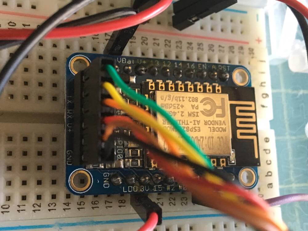
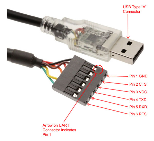
Step 1. Connect your FTDI cable to the board, with the black wire aligned to “GND” pin.
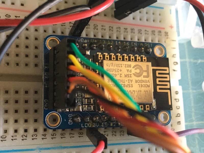
Each FTDI pin has a role to play in connecting to the board. Gearmo has a diagram that explains in full detail which wire corresponds to which assignment. The CTS and RTS pins are not always needed, but you can connect them nonetheless.
Note: Some controller boards require 3.3 volts when being programmed over FTDI. Make sure that your cable has a 3.3- to 5-volt regulator built in.
Step 2. In the Arduino IDE, under “Tools,” ensure that you have the following settings:
Board: “Adafruit HUZZAH ESP8266”
CPU Frequency: “80 MHz”
Flash Size: “4M (3M SPIFFS)”
Upload Speed: “115200”
Port: <varies by user>
Programmer: “AVRISP mkll”
Your port will be a USB one, not a Bluetooth one.
Sometimes I have run into issues where the HUZZAH board’s selection does not work right away. Switching to “Generic ESP8266 Module” and back seems to fix this.
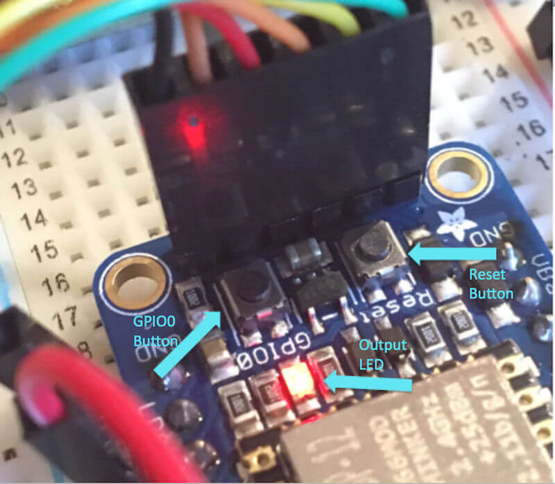
Step 3. In order to upload the code, you have to put the board into boot mode (waiting for code to be transmitted). The Adafruit folks have been kind enough to put two tactile push buttons on the board at the base of the FTDI connection to facilitate this. Follow these steps:
- Hold down the “GPIO0” button, which will cause the red LED to be brightly lit.
- While still holding this button, click and hold the “RESET” button. This will make the blue Wi-Fi LED blink once.
- Release the “RESET” button, but continue holding down the “GPIO0” button.
- Release the “GPIO0” button, which will dim the red LED. The board is now waiting to receive code.
Step 4. In the Arduino IDE, click the arrow button (for uploading). This will compile the code and start pushing it to the board. Here, you could possibly encounter two types of errors:
- a code error, including a runtime and syntax error;
- an upload error;
The first kind can be caused by errors in your code, including a misspelling, an infinity loop, incorrect logic or something else. Follow the error message and line number to identify the issue.
The second kind could be caused by a variety of issues:
- Have you selected the correct board and port?
- Did you put the board in boot-load mode?
- Is your wiring correct?
- Etc.
Follow the previous steps in this article and the connections outlined in part 1 of this series to troubleshoot wiring and connectivity issues.
If everything is wired and coded correctly, you should see a success message informing you that the code upload has completed (a “100% upload completed”).
The last step is to create the corresponding feed and dashboard on Adafruit IO, so that you can start visualizing the data!
Setting Up Adafruit IO
In the section “Preparing the Software Environment” above, I discussed creating an account on https://io.adafruit.com and obtaining a token (AIO key). In this section, we will learn how to create a feed to receive data from the board and how to build a simple dashboard to visualize the data in real time (see annotation 3 in the graphic below).
Setting Up The Feed
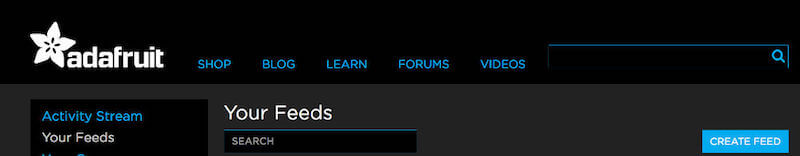
Step 1. After you log in, click on “Your Feeds” in the menu on the left.
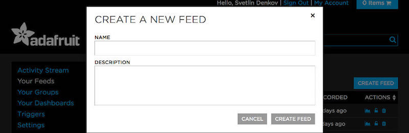
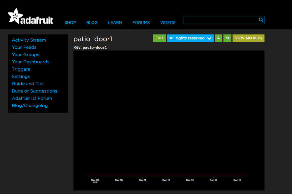
Step 2. Click on “Create Feed” and enter a name and description. The name should match the name you gave your feed in the Arduino sketch code (patio_door1).
Step 3. Once you create your feed, you can access it. This will enable you to change the stream to “Public” or “Private” (green lock icon), to view data from the feed visually or as a list, and to download the data locally.

Adafruit has a full walkthrough on creating a feed.
Building The Dashboard
Next, we will build a dashboard with some blocks and attach the feed to these blocks under “Your Dashboards.”
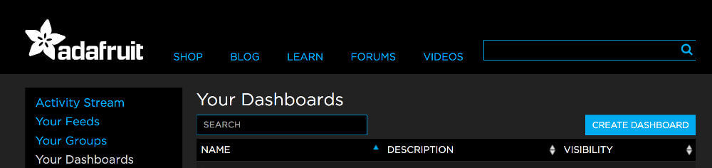
Step 1. In the left-hand menu, click on “Your Dashboards.”
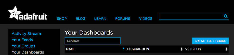
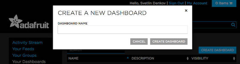
Step 2. Then, click on “Create Dashboard” and enter a name for the dashboard. This name will not be used anywhere in the code, but still use a value that you can easily identify.
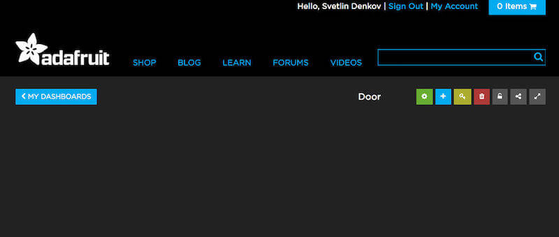
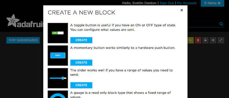
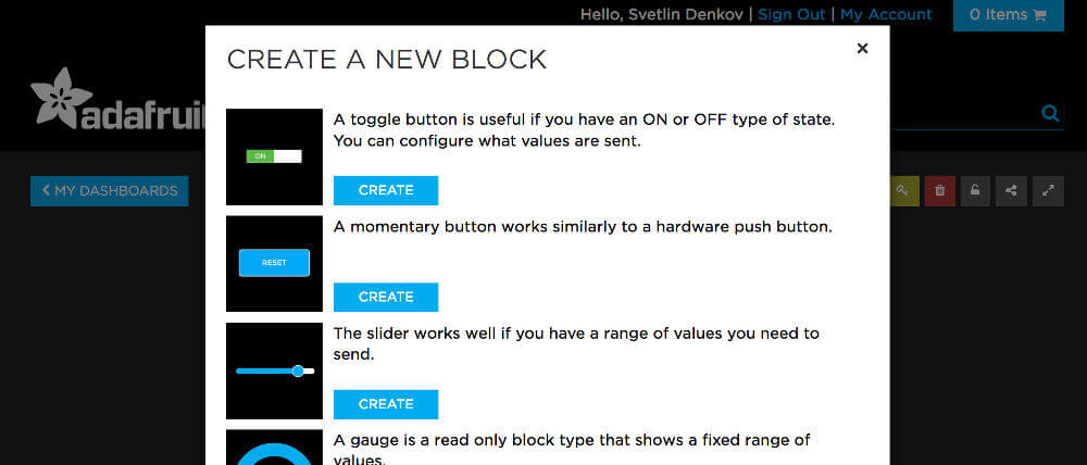
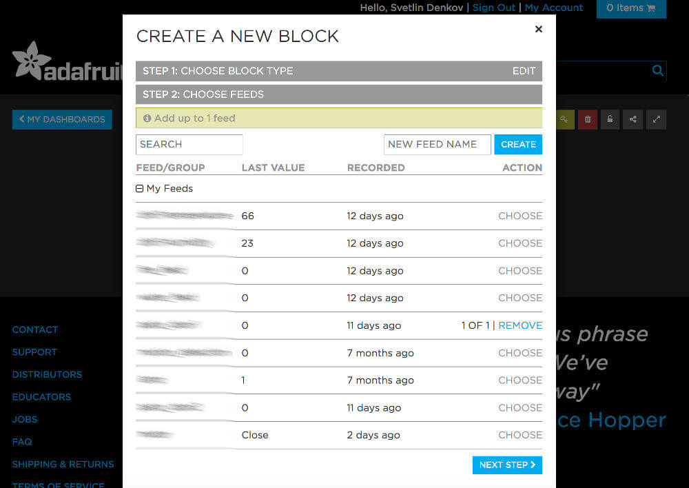
Step 3. Once you create the dashboard, you will see a blank page. It is time to add blocks that will represent the data. Click on the blue + icon to add a new block, then select the “Gauge” type (fourth one down). This will help set up the visual representation.
Step 4. In the modal window, like in step 2 of the block configuration, select the feed that you previously created (patio_door1). This will help tie the data to the visual representation.
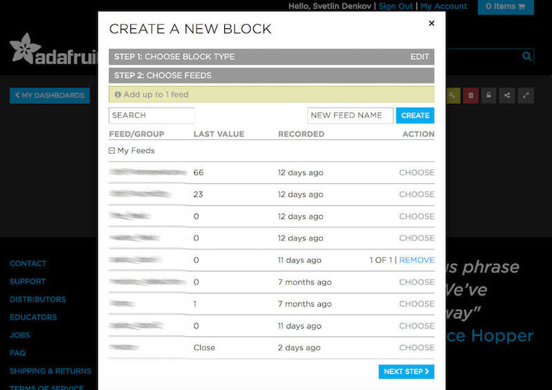
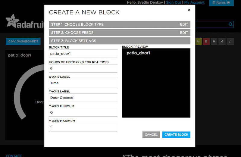
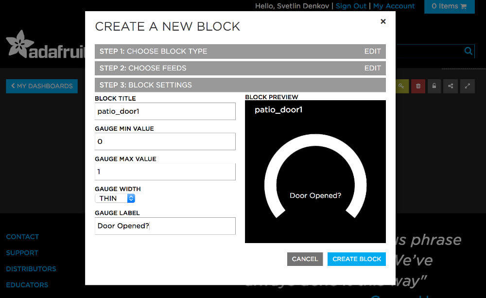
Step 5. In the last step of the block configuration, you can specify some additional UI aspects of the block. In this case, ensure that the y-axis’ “min value” is 0 and its “max value” is 1, so that it matches the Arduino sketch code.
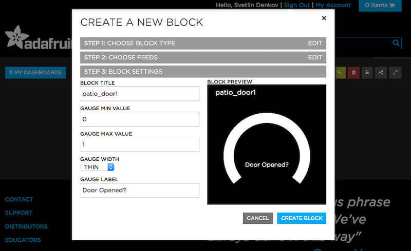
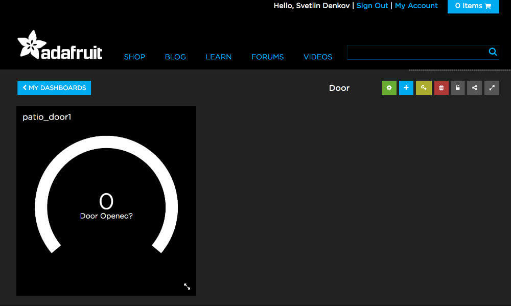
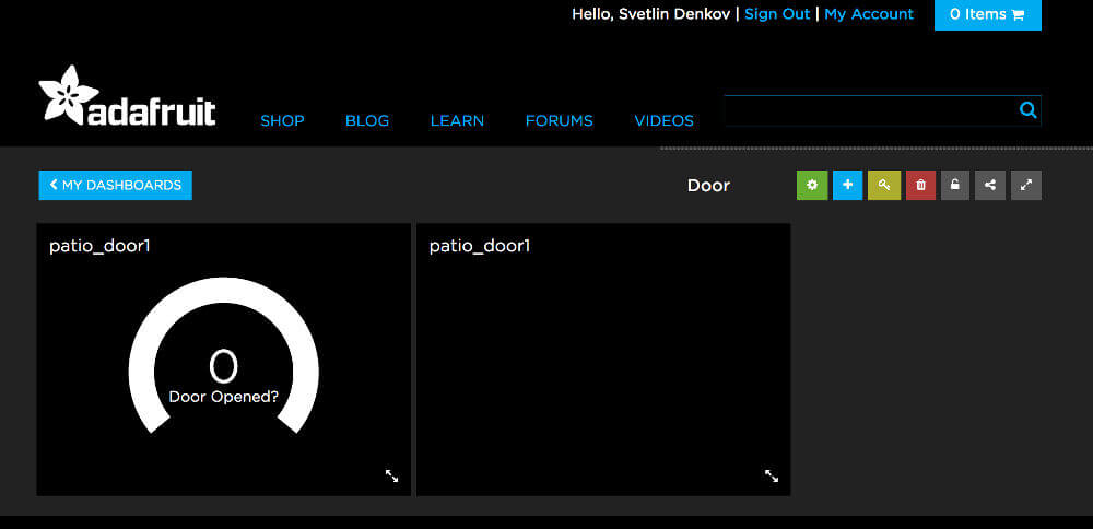
Step 6. Now you will see a visual representation of the gauge block. If your wired rig is plugged into power and is already mounted to the door (with the magnet installed), then upon opening and closing the door, you should observe the gauge turning solid blue (1 means opened), then white again (0 means closed).
Note: From this screen, you can choose to make your dashboard public. The only advantage to doing this is that you will be able to access the dashboard via its link on your device and not be prompted to log in with your Adafruit credentials every time. Find a good balance between privacy and ease of access!
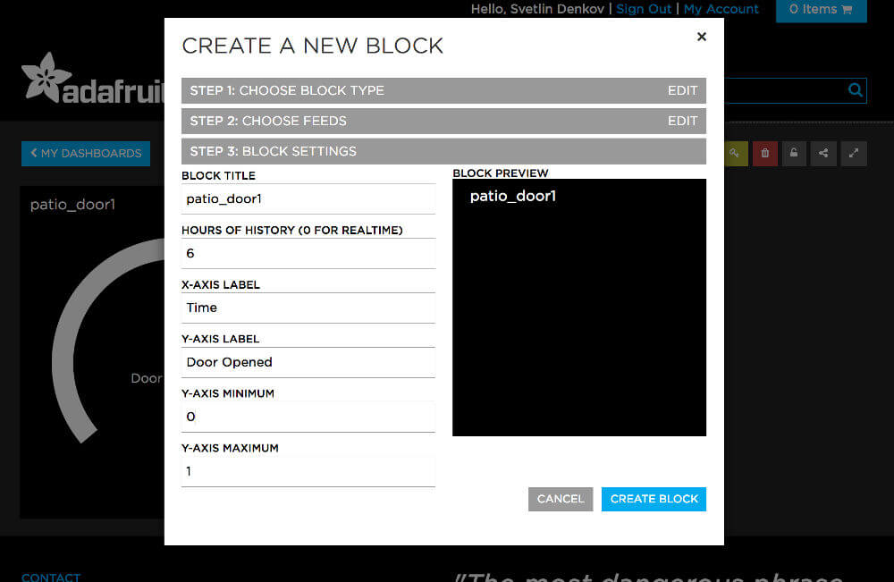
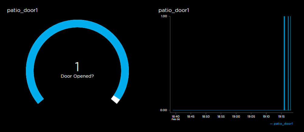
To show progress over time, you can add the “Line Chart” block, which has a very similar setup.

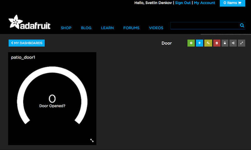
Here is an example of what the dashboard looks like after having received some data:
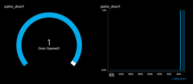
Adafruit has a full walkthrough on creating a dashboard.
Notes On Security
MQTT Connectivity
MQTT is not a very secure protocol. This article, as well as many online tutorials, provide code that uses its unsecured version to make it easier for the end user to learn.
According to MQTT.org, the protocol passes in clear text the password and username associated with the MQTT authentication. That, in and of itself, is not a problem if you are using a secure Wi-Fi network with WPA2 encryption.
Nevertheless, better to be safe than sorry. In a post on its IO blog, Adafruit discusses how you can secure communication to and from MQTT using SSL (a way of establishing an encrypted link between the server and client). Sample code is even included in the MQTT library, which you can access in the Arduino IDE via “File” → “Examples.” I have also put a complete sketch based on this code in Dropbox.
Do your research before hooking devices to the cloud using IoT technologies! Protect your privacy and data!
Your Data
With the current approach, your data gets sent to Adafruit’s servers. There is an alternative method, which, while still accessing Adafruit, gives you a little more control over where your data resides; it uses a local copy of the Adafruit IO server.
This requires a lot more setup up front, but if you are dealing with sensitive data, it is worth researching this option. Adafruit provides an explanation and the associated code.
Note: As a rule of thumb, I try not to pass data to Adafruit IO that I would not be scared about if it suddenly became public. Figure out how big of a priority this is for you!
Feeds And Dashboard Visibility
Earlier, I mentioned that dashboards can be made public or private, which controls who has access to them. Private dashboards require your Adafruit IO token to be viewed, while public ones can be accessed by anyone as long as they have the link to the dashboards. Additionally, feeds can also be made public or private.
Testing The Secure Code
There are ways you can double-check whether the secure code is indeed encrypting connections to Adafruit IO. By the very nature of how routers work, if you are on the same network as your rigs, you will not be able to see their traffic with tools such as Wireshark. If your router supports it, you can use its monitoring mode to see what data is flying back and forth.
I sought an alternative method to do that and stumbled upon the following flow:
- Set up a Raspberry Pi 3 board.
- Convert it to an access point (router).
- Use Wireshark to collect and view the data.
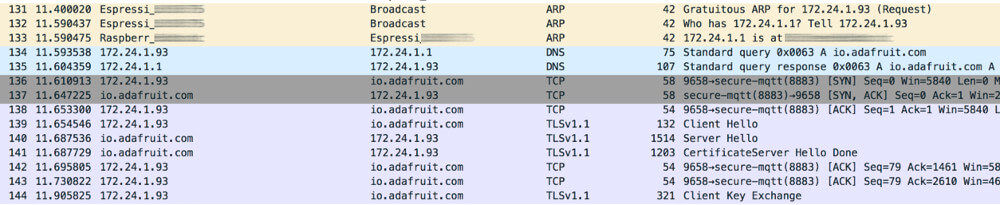
If you’ve done everything correctly, once you open the .pcap file (the capture of your data) in Wireshark on a Mac or Windows, you should see something like this:
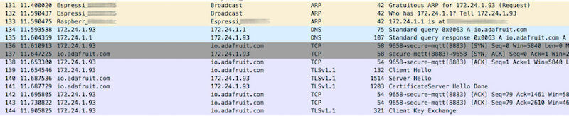
In a nutshell, this is what happens:
- yellow lines. Raspberry Pi is trying to look up the rig (which has a physical MAC address) from its network IP address (
172.24.1.93) and tells it that the Raspberry Pi is the router. - blue lines. Domain Name Service is a service for assigning human-readable URLs to IP addresses. In our case, the Pi is helping the rig look up which IP address
io.adafruit.commaps to. - gray and purple lines. A secure MQTT connection is established between the rig and
io.adafruit.com, and data starts being transmitted between the two.
Going Beyond
This setup will give you a basic sensor rig, which you can deploy anywhere within your home. However, this is only the beginning. You can expand your IoT network by doing several things:
- You could add multiple other sensors, with one or more of them being added to the same dashboard. Check out Adafruit’s growing collection of IO tutorials for inspiration.
- You could either use Adafruit’s built-in trigger functionality to capture events and respond to them accordingly or use the IFTTT service and its Adafruit channel to enable event-related messaging to a mobile device. Adafruit has a full walkthrough.
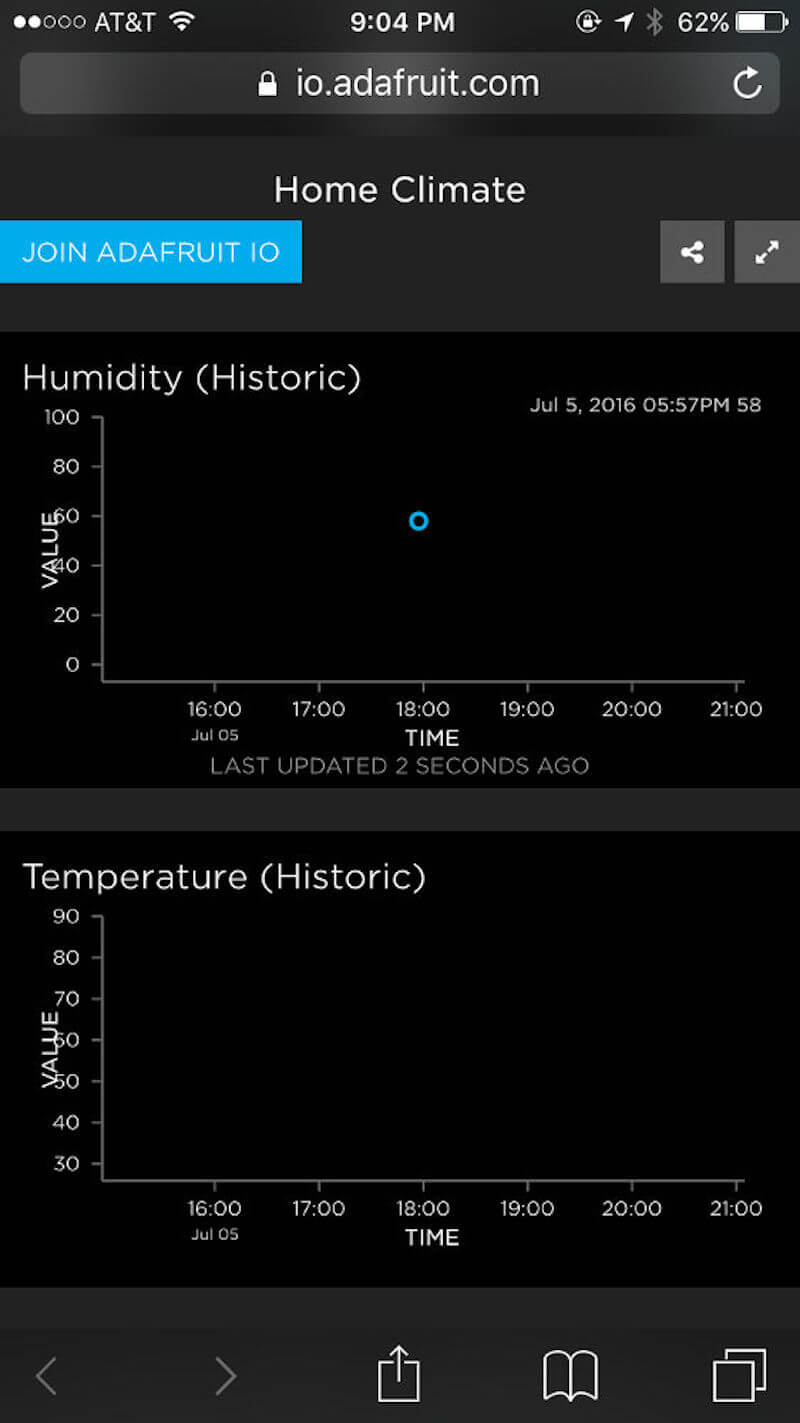
- You could open the dashboard pages on your favorite mobile device and save shortcuts to these URLs directly on your phone for real-time access.
Lessons Learned And Troubleshooting
Adafruit IO is but one solution for getting IoT connectivity. While it primarily targets the individual consumer, with time, this platform could mature to become business-capable.
The fact that it has so much functionality, with a growing list of features, makes the beta very impressive. Of all the platforms I’ve looked into, this one is the most user-friendly and has the strongest customer support.
As with other IoT platforms, it is not perfect. I did run into some problems with both the hardware and software, which I’d like to detail here, along with how I solved them, to save you some time.
Pushing Code
- At times, the Arduino IDE loses track of the USB port assigned to the currently plugged-in board. Restarting the computer usually solves that.
- Starting with version 1.6.8, I have noticed longer initial loading times of the application. This could very easily be related to the operating system.
- As outlined earlier, despite having the right settings in the IDE and FTDI connection, sometimes the code does not get pushed and throws an error. Switching to a different USB port or using the generic version of the ESP8266 in the “Settings” solves this.
Adafruit IO And Sensor Errors
- Several times I ran into an issue where my dashboards showed “[object Object].” I found this to be an error with the MQTT broker, which has been solved since.
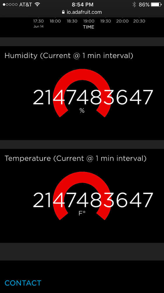
- Periodically, I get wrong data. I found out that a sensor not making good contact with the wires causes this. The mobile screenshot below shows another rig — an error only exhibited by my DHT11 humidity and temperature sensor!
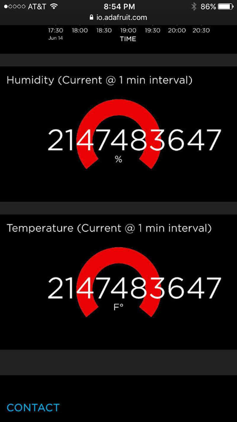
Nothing captures your attention like red bars. (View large version) - Using the “Line Chart” block is tricky. I have noticed at times that the line connecting the different data points just disappears. This has been observed on both mobile and desktop devices across different browsers. I attribute this to the UI still being in beta.
Conclusion
In my effort to solve a personal challenge (building a smart home system), I ventured to learn about IoT, hardware and code. This led me to learn a particular platform (HUZZAH and Adafruit IO), and I also ended up with an affordable and scalable solution that is up and running.
After completing this effort, I continued to research other platforms and try out Raspberry Pi, Particle and others. With each new platform, I saw more and more opportunities, which we can group into two areas: You could learn a new skill set that expands your prototyping expertise, and as a designer, these side projects could translate into solutions that address client problems:
- Proving a capability internally to grow an area of expertise within your place of employment;
- Demonstrating a proof of concept in a pitch to win new client work;
- Prototyping hardware for an existing project before going to a commercial product, thus saving the client time and money.
IoT is a vast topic, and there are many ways you could approach it. Find an area that you are passionate about. It is best if it relates to a problem you are currently facing and you use it as an opportunity to learn new skills. It is an exciting journey, and you don’t have to travel it alone. The benefits outweigh the anxiety of jumping in. So, jump in!
Resources
Arduino IDE
Adafruit
MQTT
- “Frequently Asked Questions, MQTT
- Wiki, MQTT
IFTTT
- IFTTT
- Adafruit Channel, IFTTT
- “IFTTT < - > Adafruit,” Adafruit Learning
Other Software Platforms
Further Reading
- Choosing The Right Prototyping Tool
- Prototype And Code: Creating A Custom Pull-To-Refresh Gesture Animation
- Prototyping iOS And Android Apps With Sketch (With A Freebie!)
- iOS Prototyping With TAP And Adobe Fireworks


